Published 03/13/2016
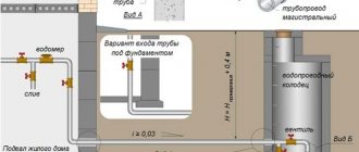
Drainage in a suburban area is a vital necessity. An autonomous sewage system, arranged in accordance with all the rules of construction science, can provide comfortable living in a dacha throughout the year, even for a large family. But whatever the method used for its installation, it is based on competent and accurate mathematical calculations. How to calculate such a sewer system for a certain number of people and is it really necessary?
How much water flows?
A country house must have a kitchen, no matter inside or as a separate building; in addition, it is impossible to do without a bathroom, while a toilet can be built directly above the cesspool. Moreover, if a certain amount of water enters the home, limited by the pressure in the pipes and, accordingly, the pressure, then much more can be drained. A striking example is a filled Jacuzzi bathtub, in which at least a couple of hundred liters of water accumulates.
If the drain capacity is insufficient, when draining from such a large tank, the liquid will certainly find other ways, for example, splashing out of the kitchen sink. In general, it is quite simple to find out the volume of drained water; there are consumption standards per person, summarized in tables, one of which will be given below.
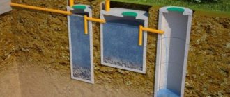
All that remains is to find out what the volume of the sump should be, where all the drains will go along with human waste products. First, you need to decide what exactly you will have on your site - a cesspool or a septic tank. The first option is cheaper, although it requires regular cleaning - according to the standards for 1 person living in the house, you need to allocate a volume equal to 0.7 cubic meters and dig a couple of cubes for reserve.
| Purpose of expenditure | Average water consumption day, liters | Day of greatest water consumption, liters | ||
| for 1 person | for 4 people | for 1 person | for 4 people | |
| Tea (3 times a day) | 1,2 | 4,8 | 1,2 | 4,8 |
| First | 0,5 | 2 | 0,5 | 2 |
| Second (3 times a day) | 1 | 4 | 1 | 4 |
| Washing vegetables and fruits | 4 | 16 | 4 | 16 |
| Washing dishes (3 times a day) | 12 | 48 | 12 | 48 |
| Washing | 10 | 40 | 10 | 40 |
| Shower | 90 | 360 | – | – |
| Toilet | 25 | 100 | 25 | 100 |
| Bath | – | – | 150 | 600 |
| Wash | – | – | 20 | 80 |
| Cleaning of the apartment | 2 | 8 | 6 | 24 |
| Total | 145,7 | 582,8 | 229,7 | 918,8 |
| 10% (hand washing, etc.) | 14,37 | 57,48 | 22,97 | 91,88 |
| TOTAL | 160,07 | 640,28 | 252,67 | 1010,68 |
As for the septic tank, when choosing a container of a suitable volume, you should remember that 1 person uses up to 200 liters of water per day (maybe more, but rarely). Here you can wash your hands, bathe, prepare food, and do laundry. Watering your favorite flower bed is not taken into account, there the water will go into the ground, it has nothing to do with drainage. Based on these data, we determine what capacity the septic tank should be for the whole family, and it is advisable to put 200-400 liters on top of the estimated volume in case guests arrive for a week. The following is the most detailed table of water consumption by climatic zones.
| Water consumers | Climate. zone | Total consumption per day | Including | ||||
| drinking, cooking/washing dishes, vegetables | personal hygiene/bath and shower | laundry | toilet flush | room cleaning | |||
| Residential buildings equipped with running water and sewerage, without bathtubs and without gas; | I-II | 85 | 6/10 | 20 | 10 | 35 | 4 |
| III-IV | 100 | 7/14 | 23 | 15 | 35 | 6 | |
| The same with gas supply; | I-II | 100 | 6/15 | 25 | 15 | 35 | 4 |
| III-IV | 120 | 7/20 | 30 | 22 | 35 | 6 | |
| water supply, sewerage and baths with water heaters running on solid fuel; | I-II | 135 | 6/10 | 15/35 | 30 | 35 | 4 |
| III-IV | 160 | 7/14 | 19/40 | 39 | 35 | 6 | |
| water supply, sewerage and baths with gas water heaters; | I-II | 160 | 6/15 | 20/45 | 35 | 35 | 4 |
| III-IV | 190 | 7/20 | 25/50 | 47 | 35 | 6 | |
| high-speed gas heaters and multi-point water supply; | I-II | 180 | 6/20 | 25/50 | 40 | 35 | 4 |
| III-IV | 210 | 7/25 | 30/55 | 52 | 35 | 6 | |
| centralized hot water supply, equipped with washbasins, sinks and showers; | I-II | 170 | 6/25 | 25/30 | 35 | 45 | 4 |
| III-IV | 205 | 7/35 | 30/35 | 47 | 45 | 6 | |
| bathtubs from 150 to 170 mm long, equipped with showers; | I-II | 215 | 6/25 | 25/60 | 50 | 45 | 4 |
| III-IV | 250 | 7/35 | 30/65 | 62 | 45 | 6 | |
| Residential buildings using drinking water from a tap located on the site | I-II | 45 | 6/9 | 18 | 9 | — | 3 |
| III-IV | 60 | 7/13 | 21 | 14 | — | 5 | |
| Residential buildings using drinking water from standpipes | I-II | 30 | 6/7 | 8 | 6 | — | 3 |
| III-IV | 40 | 7/8 | 11 | 9 | — | 5 | |
Table of climatic zones by temperature conditions
| Climatic region | Average monthly air temperature in January, °C | Average monthly air temperature in July, °C |
| l | from -14 to below -28 | from 0 to +21 |
| ll | from -3 to -20 | from +8 to +21 |
| lll | from -5 to -20 | from +21 to +27 |
| lV | from -12 to +6 | from +21 up +31 |
CALCULATION OF THE SEWER SYSTEM
The task of the calculation is to select the diameters and slopes of sewer network pipelines that ensure the removal of wastewater from sanitary fixtures and their discharge into the city sewer in gravity mode. It is recommended to calculate the sewerage system of a residential building in the following sequence.
1. An axonometric diagram of the building’s sewerage system is constructed (if there are several outlets in the building, only the part of the building’s sewerage system that operates on one outlet, farthest from the city sewer, is calculated).
2. Without calculation, the diameters of floor drain lines are assigned, if there is a toilet - 100 mm, if there is no toilet - 50 mm.
3. The diameter of the riser is assigned to be no less than the largest diameter of the floor drain lines and its capacity is checked.
The maximum throughput of a riser with a diameter of 100 mm with branch lines also 100 mm and a connection angle of floor branches of 90° is 3.2 l/s, with corresponding diameters of 50 mm - 0.8 l/s.
The sewer system collects wastewater from cold and hot water supply systems and is designed to handle the total water flow qtot, l/s,
, (3.1)
where = 0.25 l/s, and – is determined in accordance with the general probability Рtot:
, (3.2)
where = 15.6 l/hour.
Estimated flow rate at the base of the riser, l/s:
qs= qtot + q0s, (3.3)
where qtot is the total maximum estimated water consumption by the devices of the calculated riser, l/s, determined by formula (3.1) for the number of devices N served by this riser (the probability Рtot was determined earlier by formula (3.2)); q0s – volley discharge of wastewater by one device, l/s, if there are toilets on the riser q0s = 1.6 l/s, in other cases - according to adj. 2.
If the calculated flow rate exceeds the maximum throughput of the riser, it is necessary to increase the diameter or change the angle of connection of the floor branches.
4. Calculation of horizontal pipelines (in the basement), outlets and yard sewer network is carried out. The calculation consists of selecting such diameters and geodetic slopes at which the speed V is at least 0.7 m/s, the filling of pipelines H/d is at least 0.3 and the condition is met
. (3.4)
In cases where it is not possible to fulfill these conditions due to insufficient wastewater flow, sections are considered undesigned and are laid with a slope of 0.03 with a diameter of 50 mm and 0.02 with a diameter of 100 mm. For calculations, tables or nomogram adj. are used. 3.
According to the hydraulic calculation data, the marks of characteristic points of internal horizontal pipelines and the tray of wells in the yard network are determined. Based on the calculation results, the elevation of the pipe tray at the entrance to the sewer collector should be higher than the elevation of the tray of this collector.
Example 1. Design and calculation of building sewerage systems.
Initial data: building according to Table 1.1, sewer depth - 4.0 m.
Solution.
Based on the analysis of the location of the risers (Fig. 3.1), the outlet towards the courtyard facade was adopted (Fig. 3.2).
Rice. 3.1. 1st floor plan
Rice. 3.2. Basement plan
An axonometric diagram of the sewerage system is shown in Fig. 3.1.
Figure 3.3. Axonometric diagram of internal sewerage
Floor branches are made of cast iron, laid directly on the floor of the corresponding floor, the diameter before connecting the toilet (along the water passage) is 50 mm, after connecting the toilet - 100 mm.
The risers are made of cast iron with a diameter of 100 mm, their exhaust part extends 0.5 m above the pitched roof. Audits are provided on the 1st, 3rd and 5th floors. Each riser collects wastewater from 20 devices, the probability of their action according to example 1 Ptot = 0.017, then N Ptot = 0.34 and according to adj. 1 α = 0.565.
Using formulas (3.1) and (3.3), the estimated flow rate at the base of the riser is determined:
qtot=5·0.25·0.565=0.71l/s; qs=0.71+1.6=2.31 l/s.
The resulting value is less than the throughput of the riser, and adjustment of the diameter of the riser is not required.
The laying of horizontal sewer networks in the basement of the building was adopted above the floor with an initial elevation of 2.00 m. Design sections 1–2–3 in the building were assigned and, according to the master plan, the yard network was traced - sections 3–КК1–КК2–КК3 (Fig. 3.4 ).
Rice. 3.4. General plan of the site
All calculations are summarized in table. 3.1.
Table 3.1
Calculation of the economic sewer network.
| Site name | Number of devices on site N, pcs. | N Ptot | ά | Design flow qs, l/s | Diameter, mm | Slope i | Speed V, m/s | Filling H/d | Section length L, m | il | Ground mark | Pipe tray mark | Pipe depth | |
| at the beginning of the section | at the end of the site | at the beginning of the section | at the end of the site | at the beginning of the section | at the end of the site | |||||||||
| Internal network | ||||||||||||||
| 1–2 | 0,34 | 0,565 | 2,31 | 0,02 | – | – | 5,0 | 0,10 | – | – | -2,0 | -2,10 | – | – |
| 2–3 | 0,68 | 0,791 | 2,59 | 0,02 | – | – | 4,5 | 0,09 | – | – | -2,10 | -2,19 | – | – |
| Taking into account the absolute elevation of the floor of the 1st floor of 51.20 m (according to the general plan), the pipeline at the exit from the building has an absolute elevation of 49.01 m | ||||||||||||||
| Yard network | ||||||||||||||
| 3–КК1 | 0,68 | 0,791 | 2,59 | 0,02 | – | – | 3,0 | 0,06 | 50,40 | 50,40 | 49,01 | 48,95 | 1,39 | 1,45 |
| KK1–KK2 | 0,68 | 0,791 | 2,59 | 0,02 | – | – | 12,0 | 0,24 | 50,40 | 50,45 | 48,95 | 48,71 | 1,45 | 1,74 |
| KK2–KK3 | 0,68 | 0,791 | 2,59 | 0,02 | – | – | 5,0 |
Based on the data in Table 3.1. and the general plan of the quarter, a longitudinal profile of the yard network collector is drawn up (Fig. 3.5). First, a profile of the earth's surface is drawn on a specified scale along the route of the yard network. Sewer wells and communications are transferred to the profile from the general plan and the lengths of the calculated sections and marks of intersections of networks with communications are postponed from the general plan. Below the profile, a form of the established form is filled out, in which the results of the calculations from the table are entered. 3.1 and data from the master plan of the quarter. Utility networks (water supply, heating networks, sewerage) must be linked to the coordinate network of the quarter.
Rice. 3.5. Profile of the yard sewer network
Due to the low flow rate, it was not possible to select slopes that would ensure the fulfillment of the above conditions. Therefore, i = 0.02 is structurally assigned.
In accordance with the initial data, the ground elevation according to the general plan at the point of connection to the collector is 50.45 m, the collector elevation is 4.0 m less than the ground elevation - 46.45 m. According to the calculation results, the yard network pipeline is adjacent to the collector at a higher elevation 48, 61 m, and operation of this system in gravity mode is possible.
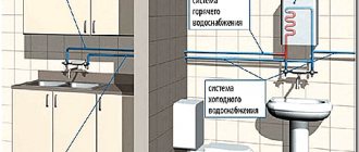
Determining the pipe capacity
In any house there must be communications through which, like arteries in the human body, water enters the premises, from where it then flows out through the sewers. It is the latter that are the sewer system. Considering that several water supply points can be operated simultaneously, for example, a shower in the bathroom and at the same time a faucet in the kitchen, it is necessary to determine in advance the sufficient capacity of the pipes.
Especially for this purpose, SNiP provides for permissible speeds of movement of wastewater, as well as limits for the filling of sewer lines and the necessary diameters for the free passage of the entire volume of water being drained.
Before calculating an autonomous sewer system in a private house, it is very important to correctly determine water consumption in order to know the number of drains and the appropriate pipe diameter for them. To calculate the drainage capacity, the formula U√(H/d)≥ K is used, where U is the speed of water movement in the sewer (minimum according to SNiP - 70 cm/sec), H is the filling value of the pipes, and d is their diameter. As for the K coefficient, it is determined by the material from which the communications are made; for glass and plastic it corresponds to a value of 0.5, and for other materials it is equal to 0.6. In general, the H/d ratio is the maximum degree of filling; the dependence of this indicator on the diameter can be found in the table.
| d, cm | h/d |
| 15-25 | 0,6 |
| 30-40 | 0,7 |
| 45-90 | 0,75 |
| Over 90 | 0,8 |
If the filling value of the pipes is below 0.3, blockages may occur, and if it is made for home sewerage above 0.6, the sewerage system will not have time to ventilate, which will lead to unpleasant odors.
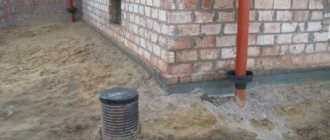
Laying an external sewer pipe
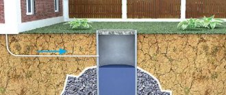
The sewer pipe from the house to the septic tank (cesspool, storage tank) should be laid at a slope of 1-2% (1-2 cm per meter of length). The diameter of the external sewer pipe should be 100-110 mm.
Slope of sewer pipes 1-2 percent
The external sewer pipe is laid 50 cm below the freezing depth of the soil. If the freezing depth is too great, the sewer pipe is insulated . When the sewer pipe is laid at a large depth (over 1.5 m), to protect the pipe and insulation from soil pressure, the pipe is placed in a protective box. Reinforced concrete trays or impregnated railway sleepers can be used as protection against soil pressure.
Reinforced concrete trays for protecting sewer pipes Reinforced concrete trays for protecting sewer pipes
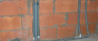
If the sewer pipe is laid through the body of the foundation, then the hole in the foundation is sealed with basalt or stone wool. Rigid sealing of a sewer pipe is not allowed due to the linear expansion of the pipe from warm sewage.
Sewer pipe socket
The sewer pipe is laid from the house to the septic tank (cesspool, storage tank) in such a way that the pipe socket is directed towards the drains. The socket is a widened end of a sewer pipe with a rubber seal into which the next section of pipe is inserted.
The external sewer pipe must be laid straight, without turns. If turns cannot be avoided, then they should be made smoother. For example, instead of using a 90-degree fitting, use two 45° fittings, or three 30° fittings.
How is hydraulic calculation made?
When hydraulically calculating sewerage, special formulas are used to select the appropriate equipment, calculate the angles of inclination of the pipes and organize the uniform movement of wastewater. However, it is known that the movement of wastewater in pipes is uneven. What is calculated using these formulas? The answer is simple: calculating the uneven movement of a fluid is too complex a mathematical problem.
table for calculating the slopes of sewer pipes
Therefore, for domestic needs, taking into account some assumptions and errors, it was decided to consider the flow of wastewater as uniformly moving in the pipe system. The formulas used for the hydraulic calculation of individual sewers are a practical compromise that allows you to obtain acceptable results without spending excessive time and effort on more accurate calculations. To further simplify the calculations, ready-made values for typical cases are given in various tables, graphs and nomograms.
Pipe selection
Sewage pipe diameters
When laying the sewer system of a private house, round-section water flows with an internal diameter of 40 to 110 mm are used, made of polyvinyl chloride that is resistant to aggressive wastewater environments. Since various plumbing and household appliances are characterized by unequal volumes of wastewater, differing in consistency and composition, pipes with the following internal diameters are used:
- washbasins, kitchen sinks – 40-50 mm;
- bathtubs, shower trays – 50 mm;
- washing machines and dishwashers – 50 mm;
- urinals, bidets – 50 mm;
- toilets – 110 mm.
If a private residential building has 2 or more floors, the upper bathrooms are connected to the lower sewers using vertically located communications - risers - with an internal diameter of 110 mm.
For the yard drainage network, a special bright orange water flow is used, having a nominal passage of 110 or 160 mm.
Initial stage of calculations
First of all, it is necessary to calculate small (up to 8 liters per second) wastewater flow rates in the initial sections of the network. To do this, designers should use the following expression:
Qк = Qв + Qok
Here Qw is summed up - the number of liters per second consumed by the fittings serving wastewater receivers in a specific section of the network, and Qok - a certain standard wastewater flow rate from a plumbing fixture, taking into account the maximum rate per second.
The formula takes the form Qк = Qв, if the wastewater flow rate is more than 8 liters per second.
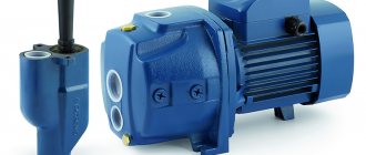
The system outlet pipe must work according to calculations
Example of a home water supply project
Back
Forward