How many rings to buy for a well
You can calculate the approximate depth of the well based on the depth of water carriers in neighboring areas, adjusted for the relief. This value is divided by the height of one ring and their approximate number is obtained for arranging a well shaft. It’s better to order not back to back, but with a small margin, so that at a crucial moment you don’t have to urgently organize the delivery of 1-2 rings to the site. For example, in the Moscow region, the depth of wells is 10-12 rings.
The seams between the installed rings must be filled with a binder solution. The use of traditional methods: tarred tow, etc. is undesirable. The use of rings with closing grooves creates a durable and waterproof joint
This is fraught with additional costs, but the main thing is that the process of lowering the rings should not stop so that the soil does not have time to jam the shaft. It holds the rings so tightly that sometimes it is necessary to compact the column from above using heavy equipment. The remaining rings can be sold to the owners of neighboring plots, used to make a reservoir for collecting rainwater, and used to build a homemade septic tank.
When constructing a well, reinforced concrete rings with perforations are used - for the influx of water through the sides of the shaft and for the introduction of water supplies. To cover the protection of the upper part from debris, special covers are cast corresponding to the diameter of the rings, with a hole and a hatch. Rings of smaller diameter are called repair rings and are used to deepen shallow wells.
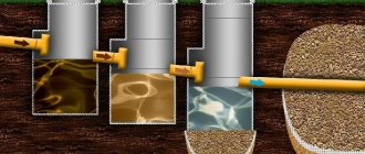
Installation of a septic tank made of concrete elements
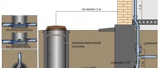
After carrying out the basic calculations, it is necessary to develop a layout diagram of the sewer system. According to existing standards, the septic tank must be located at least 5 m from the boundaries of the site, 10 m from the house to prevent erosion of the foundation, and also 30 m from the nearest surface reservoir.
Do not forget that the maximum distance from the water supply source is also required. If there is a slope on the site, the septic tank must be located below the drinking water collection point. After choosing a location, installation of a treatment plant for a private house or cottage is carried out in several stages.
Soil development
When installing a septic tank that includes several chambers, it is best to prepare one common pit. To carry out all the work, it is more economically feasible to hire special equipment. In this case, soil development will take no more than 2–3 hours.
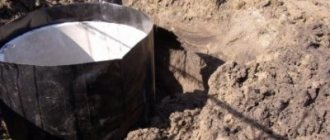
Installation of the receiving chamber and settling tank must be carried out on a concrete base to prevent the flow of untreated wastewater. Therefore, the bottom of the pit in the places where these wells are installed is compacted, a layer of roofing material is laid as waterproofing, and a small pedestal is poured.
At the site where the filtration well is installed, the soil is not compacted; part of it is replaced with a crushed stone cushion, the height of which must be at least 50 cm. Such a filter made of coarse aggregate will allow water to flow freely into the ground, and will also serve for final purification of water.
Creating cameras
When installing the rings, you will also need special lifting equipment, for example, a small truck crane or manipulator. First, the skeleton of each well is assembled by installing the estimated number of rings. For better connection, the rings can be laid on mortar or special glue.
The places where the rings connect to each other and to the base are carefully sealed with mortar. For additional waterproofing, liquid glass can be added to the mixture at the rate of 10 g of additive for every 1 kg of cement.
For additional protection of the well, it is better to treat the joints of the elements with mastics or painting composites for waterproofing from the outside and inside. Such finishing will not interfere with the entire body of the well.
Special reinforced concrete covers with holes for a hatch and ventilation pipe are installed on top of each chamber.
Connecting cameras into a single system
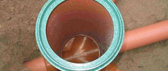
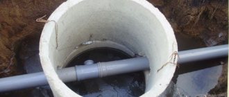
After installing the rings, it is necessary to connect all the elements of the septic tank into a single structure. To make pipe routing easier, it is best to order rings with side holes. Otherwise, niches for the pipeline can be prepared using a special concrete bit with a diameter of at least 114 mm or manually.
It must be remembered that a septic tank made of rings is designed for independent movement of wastewater, so the installation of pipes must be carried out very carefully. The sewer pipe must be laid in the receiving chamber with a slope of 2 cm for each meter of length. That is why you should not move the sewer too far from the house.
The connecting pipes between the chambers must be located below the level of the entrance of the main drains, otherwise the flow will become cyclic and the septic tank will stop working. The entry points of all pipes must be carefully sealed with mortar and additionally treated with waterproofing and sealing compound.
Backfilling the septic tank
After installation of all elements of the system, the pit is backfilled. For these purposes, it is also best to hire special equipment, because manual labor will require no less payment than renting a tractor with a bucket or a loader.
The septic tank must be backfilled with soil removed during the construction of the pit. If the clay content is high, you can add a little sand, which can be more evenly distributed around the structure. After backfilling is completed, the septic tank is ready for use.
With proper calculation and installation, a septic tank made of concrete rings can become a very effective and inexpensive treatment system for a country or private home, which will serve its owners for at least 50 years.
Why are additional rings needed?
When it is impossible to install conventional ones, additional rings are used for the well. They solve problems caused by the width, slope or height of a standard through-hole. The height of the additional ring is less than 40 cm, so it allows you to bring the shaft to the desired height if this is not possible with a regular one. From a specialized company, you can order additional rings based on individual measurements so that they exactly match the structure being built.
When designing a well, much attention is paid to the decorative component. Rarely do owners agree to simply have a head sticking out on the property, covered by a hatch
For such cases, the upper rings with a beautiful relief are cast.
What types of rings are there for a drinking well?
There is no single standard that regulates the sizes of rings for wells. To line a well shaft, rings with an internal diameter of 90-100 cm and a height of 70-100 cm are used. These values are dictated by practicality: if you take less, it will be inconvenient to dig inside, if more, the amount of manual labor will increase significantly. The larger the ring, the heavier it is, which means additional shipping costs.
Concrete rings, indistinguishable from the outside, differ in casting technology and composition:
- Drinkable;
- Sewer;
- Gas pipelines.
The most stringent requirements are imposed on water intake rings. Each ring must have a standard marking. Before going on sale they are subjected to production tests.
You need to order reinforced concrete rings only from certified sellers. Under the guise of well products, you can unknowingly buy simple technical ones, which contain harmful impurities
High-quality reinforced concrete rings have many advantages:
- Lowest price (in comparison with a wooden frame or rubble masonry);
- Solidity;
- Easy to install and repair;
- Resistance to soil pressure;
- Wide range.
For strong and durable well concrete rings, a frame made of reinforcement is used, filled with a mortar of M-500 cement. The wall thickness is from 10 cm.
When producing rings for non-food purposes, casting molds are lubricated with petroleum products. Along with them, an oil film may appear in the new drinking well, which is not easy to get rid of.
In industrial production, vibration is used to compact the solution in the molds, but the surface of the finished ring retains some porosity, so it is impossible to completely clean it of oil.
TRANSPORTATION AND STORAGE
4.1. Transportation and storage of structures - in accordance with GOST 13015.4 and this standard.
4.2. The structures are transported and stored in working position.
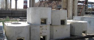
4.3. Structures should be stored:
- working chambers - in one row;
- wall rings - in two rows in height in accordance with the diagram shown in Fig. ;
- support rings and plates - no more than six rows in height on spacers (linings) in accordance with the diagram shown in Fig. .
Scheme for storing wall rings of wells
Scheme for storing floor slabs and well bottoms
— gaskets (linings); 2
- mounting loops
Other storage schemes are permitted, provided the safety of structures is ensured and safety requirements are met.
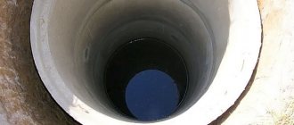
Installing rings in a well shaft
After a promising location for building a well has been identified, a small area is cleared and a circle is marked for excavation. The diameter of the laid shaft should be several centimeters larger than the purchased rings. A small gap will ensure free descent of the column into the prepared pit. After digging, the soil around the mine will settle and compact naturally. This takes several months. You can’t dig a shaft end-to-end so that the rings don’t get pinched.
There are several methods for lowering reinforced concrete rings into a well. They differ in complexity, required equipment and safety. In the first case, a trench is dug and deepened at a marked place, and the first ring is lowered into it. Then the worker digs inside it, gradually deepening the bottom and evenly removing soil from under the walls. If there is a risk of uneven descent, pieces of logs are hammered under the ends of the ring to prevent premature movement. The soil is loaded into a bucket, which is pulled out with a collar or winch. As soon as the first ring has sunk sufficiently, the next one is installed on it.
Work inside the mine is difficult; there may be a shortage of oxygen at depth. For digging and lowering you need at least two workers, and optimally three. One works in the mine, the second lifts the soil upward, the third has time to rest. Standard size rings can be lowered without additional equipment. Using a winch or truck crane significantly speeds up the process. The described method is the safest.
When digging a shaft, you need to constantly monitor the verticality of the recess so that you don’t get a slant or a wave. In such a place, the rings either stop or fall to one side. Correcting the situation is problematic
Even if the mine is lined with rings as it goes deeper, there is a chance that quicksand will open. This is a fluid mass of suspended soil particles. A weak quicksand will cover the bottom with sand or clay, depending on its composition, while a powerful one can turn out and carry away rings.
Second method: First, the shaft is completely excavated until the water begins to rise quickly. Then all the rings are lowered into it one by one. The worker has more space at the bottom, so choosing soil is easier, but there is a great danger that a collapse will occur or quicksand will be revealed. This method is only suitable for dense clay soils that are not prone to crumbling and landslides.
The price for negligence can be very high. When lowering the rings into the finished shaft, they cannot simply be dropped; for high-quality and accurate work, a winch will definitely be required
To prevent the rings from moving during construction and operation, they are produced with a groove for mutual closure. The shaft will be more stable, and the waterproofing seams will be more reliable. Simple rings are reinforced with reinforcement brackets or strips of metal.
Established Standards
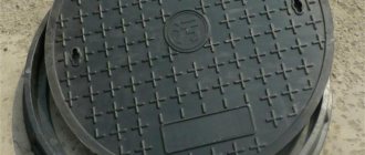
Also, a round hatch diameter of 700 mm, or a rectangular one, with sides of at least the same size, is provided in the well ceiling.
In general, there is GOST sewerage wells, No. 8020-90, which establishes standard dimensions of elements for mines.
The following abbreviations apply:
- KFK - well of the household (fecal) network
- KDK - working chamber of the intra-block network
- KLK – storm sewer chamber
- KLV - the same, with the function of receiving water
Depending on the purpose, on what series of sewer wells is provided for a given type, they can have the following dimensions:
| Device type | Series | D internal | D ext. | Ring height H |
| KFK and KDK | KDK10 | 1000 | 1160 | 1270 |
| KFK10 | 2410 | |||
| KFK13 | 1250 | 1410 | 2630 | |
| KFK15 | 1500 | 1680 | 2870 | |
| KFK20 | 2000 | 2200 | 3110 | |
| KLV and KLK | KLV8 | 820 | 960 | 1550 |
| KLK10 | 1000 | 1160 | 1800 | |
| KLK13 | 1250 | 1410 | ||
| KLK15 | 1500 | 1680 | 1980 |
Lattice storm sewer hatch
In this case, GOST allows the height of the rings to be increased to 1790 mm in increments of 300 mm. Neither SNiP nor GOST for reinforced concrete sewer wells regulate the volume as such - but there are requirements for a well height of 1800 mm, with a depth of less than 1.2 m the diameter of the well can be 1000 mm, and with a depth of 3 m or more - from 1500 mm or more.
Wells for storm drainage can be equipped with a standard size lattice hatch, which allows for the function of catchment (KLV series).
At the same time, the location of the hatch also has its own requirements: it can be installed flush with the surface on asphalt or concrete roads, it must protrude from the surface by 5-7 cm in the green zone, and by 20 cm in undeveloped areas.
Also, if necessary, hatches are equipped with locking devices.
Characteristics
1.3.1. Designs must meet the requirements of GOST 13015:
— in terms of strength, rigidity and crack resistance, while there are no requirements for testing structures by loading;
- according to the actual strength of concrete (at design age and tempering age);
— frost resistance and water resistance of concrete;
- according to the thickness of the protective layer of concrete to the reinforcement;
— to steel grades for reinforcing and embedded products, including for mounting hinges;
- for protection against corrosion.
1.3.2. Structures should be made of heavy concrete in accordance with GOST 26633 classes or grades of compressive strength specified in the working drawings of the structures.
1.3.3. The normalized tempering strength of concrete is taken equal to 70% of the class or grade of concrete in terms of compressive strength.
The specified standardized tempering strength of concrete can be reduced or increased in accordance with the requirements of GOST 13015.
1.3.4. The water absorption of concrete structures must correspond to that established by the design documentation of a particular structure or specified when ordering structures.
1.3.5. For the reinforcement of structures, the following types and classes of reinforcing steel are used:
— thermomechanically strengthened rod of the At-ShS and At-lVC classes according to GOST 10884;
— hot-rolled rod of classes A-1, A-11 and A-111 according to GOST 5781;
— reinforcing wire of class VR-1 according to GOST 6727.
1.3.6. The shape and dimensions of reinforcement and embedded products and their position in structures must correspond to those indicated in the working drawings.
1.3.7. Welded reinforcement and embedded products must meet the requirements of GOST 10922.
1.3.8. In cases provided for by the working drawings of wells, running brackets must be installed inside the wall rings, located along the height of the ring every 300 mm and protruding from the inner surface of the rings by 120 mm.
Running brackets should be made of reinforcing steel class AI or A-P according to GOST 5781.
By agreement between the manufacturer and the consumer, wall rings may be manufactured without running brackets, provided they are installed on the construction site.
1.3.9. The running brackets must be protected from corrosion in accordance with the instructions of the working drawings of the wells.
1.3.10. The values of actual deviations of the geometric parameters of structures should not exceed the limits specified in table. 1.
Table 1
In millimeters
| Name of deviation of geometric parameter | Name of geometric parameter | Prev. off |
| Deviation from linear size | Height (thickness) of the structure: | |
| up to 180 | + 5 | |
| » 300 | + 8 | |
| » 1000 | + 10 | |
| St. 1000 to 1600 | + 12 | |
| » 1600 » 2500 | + 15 | |
| » 2500 | + 20 | |
| Inner diameter of working chambers, wall- | ||
| outer and support rings, outer diameter of floor slabs and bottom, diameter of manholes and holes for pipelines: | ||
| up to 1000 | + 6 | |
| St. 1000 to 1600 | + 8 | |
| » 1600 » 2500 | + 10 | |
| » 2500 | + 12 | |
| Length and width of base and road slabs | + 10 | |
| Position of holes and cutouts | 10 | |
| Deviation from flatness of the lower surface of floor slabs (when measuring | Outer diameter of floor slabs: up to 1000 St. 1000 to 2500 » 2500 | 4 |
| from a conventional plane passing through three points) | 6 8 |
1.3.11. Requirements for the quality of surfaces and appearance of structures are in accordance with GOST 13015. At the same time, the quality of surfaces of structures (with the exception of joint surfaces) must meet the requirements established for category A6. The surfaces forming a joint between structures, which are sealed at the construction site, are subject to the requirements established for category A7.
It is allowed, by agreement between the manufacturer and the consumer, to apply to all surfaces of working chambers, wall and support rings the requirements established for category A7.
METHODS AND TECHNIQUES OF WORK
The installation of concrete preparation and trays is carried out by unit No. 1 of the following composition:
concrete worker 4 r. — 1 person (1) link;
concrete worker 2 r. — 1 person (2).
The concrete mixture delivered to the well installation site is supplied by the concrete worker (2) to the laying site along a wooden tray. A concrete worker (1) located in the pit places concrete at the base of the well and compacts it using a hand tamper.
After the concrete preparation is installed, a reinforcing mesh is laid on it and the tray is concreted. Cleaning the bottom and slopes of the pit, preparing the base for the well, sealing the pipes in the tray and installing the well elements is carried out by unit No. 2 of the following composition:
truck crane operator 5 r. — 1 person (1)
pipe layer 4 r. — 1 person (2) link
pipe layer 4 r. — 1 person (3)
pipe layer 3 r. — 2 people (4;5)
pipe layer 2 r. — 1 person (6).
Before starting work on constructing a well, the pipelayer (4) cleans the slopes and bottom of the pit, checks compliance with the design of the bottom elevation and the steepness of the slopes of the pit.
Pipelayers (6 and 5) are busy working to saturate the soil at the base of the well with bitumen. The loosened and bitumen-impregnated soil is leveled and compacted using hand tampers.
Pipelayers (2 and 3) are busy preparing for the installation of reinforced concrete rings of the well, sealing pipelines into the tray, installing the well rings and installing a clay castle at the junction of the pipelines with the tray.
Arrangement of workers during the installation of wells: the pipe layer (5) is at the top and is engaged in slinging loads, the pipe layers (2 and 3) are installing the well elements in the pit, the pipe layer (4) is preparing the bases of the wells for installation and grouting the seams of the mounted well elements, and the pipe layer (6) - for auxiliary work (cleaning the reinforced concrete rings of the well from contamination, carrying materials, tools, etc.).
The pipe layer (5), having secured the lower ring of the well with a four-legged sling, gives a signal to the crane operator to lift the load. After a test lift to a height of 0.1-0.2 m above ground level, the pipe layer (5) checks the reliability of the sling and allows the ring to be delivered to its installation site. Pipelayers (2 and 3), having accepted the reinforced concrete ring of the well, install it on the tray with mortar. After verifying that the ring is installed correctly, it is unslinged and a signal is given to the link members to remove the slings and prepare for the installation of the next ring.
The cement mortar protruding from under the rings (during their installation) is removed, and the seam is thoroughly rubbed inside and outside the well. The correct installation of the rings is checked by level and plumb. The final well installation operations are the installation of the hatch (cage and cover) with the sealing of the cage on the neck with M-50 cement mortar and the installation of a clay castle.
Insulation of reinforced concrete well rings with bitumen is carried out by unit No. 3, consisting of two insulators of the third (1) and second (2) categories.
The insulator (2) heats the bitumen in a mobile boiler, and the insulator (1) prepares the reinforced concrete rings for insulation (cleaning off contaminants, applying a primer, etc.).
After the primer has dried, insulators (1 and 2) use brushes to apply hot bitumen to the inner surface of the rings at a distance of 5 cm from the edges.
After installing the well rings and sealing the joints, insulators (1 and 2) prime the joints and apply bitumen to them.
Hydraulic testing of the well is carried out by link No. 2 by filling it with water and observing its leakage. A preliminary test is carried out before filling the well with soil and is aimed at identifying visible water leaks, and the final test is to determine the amount of leakage, which should not exceed 60 l/day for a given well.
The well is filled with soil in layers using a bulldozer. Each layer is compacted by a pipe layer (4) using a pneumatic rammer.
The completion of the well construction is the installation of a concrete blind area around the neck. The concrete blind area is arranged by the concrete workers of unit No. 1 in the following order: the concrete worker (2) scatters crushed stone around the neck and then compacts it, and the concrete worker (1) lays concrete on the prepared base and levels it.
Schedule for the construction of prefabricated reinforced concrete wells with a diameter of 1.0 m and a depth of 3.0 m on sewer networks
Note. The labor costs of the truck crane operator are not taken into account in the schedule.
SAFETY
Work in excavations with slopes that have been moistened after soil removal is permitted provided that precautions are taken against soil collapse, namely:
a) a thorough inspection by the workman or foreman before the start of each change in the condition of the soil and its artificial collapse in places where “peaks” and cracks are found at the edges and on the slopes;
b) temporary cessation of work in the excavation until the soil is drained if there is a danger of a collapse;
c) local reduction of the steepness of the slope in areas where work in the excavation is urgent;
d) prohibition of the movement of vehicles and mechanisms within the collapse prism.
When installing a well, a person from among the engineering and technical personnel must be appointed, responsible for the safe execution of work on moving and installing loads with cranes.
All lifting mechanisms and devices (crane, slings) must be periodically checked before starting operation, as well as during operation, in accordance with the rules of Gosgortekhnadzor.
When installing well elements, the edges must work on outriggers. The lifting capacity of the slings must correspond to the weight of the load being lifted. Lifting and moving well elements should only be done after checking the correctness and reliability of their slinging. When lifting, moving and lowering the well elements with a crane, it is prohibited for people to remain in the area of its operation; the well elements must not be allowed to be moved above the pipelayers’ workplace. The supplied well element should be lowered above the place of its installation by no more than 30 cm, and only from this position the pipelayers direct it to the design position.
Workers who are at least 18 years old, who have passed a medical examination and trained according to a special program approved by Gosgortekhnadzor and certified by the qualification commission with the issuance of certificates, are allowed to work as a sling operator.
Unslinging the installed well elements is allowed only after they have been firmly and securely fastened. It is prohibited to swing a suspended load and leave it hanging without supervision, as well as to carry out installation in a wind force of more than 6 points.
The operation of a jib crane near power lines is permitted only if the horizontal distance between the extreme point of the mechanism, cargo ropes (cables) or load (at the greatest reach of the working body) and the nearest power line wire is not less than that specified in Table 1.
Permissible horizontal distance from operating machines to power cables
Table 1.
| Transmission line voltage in kV. | up to 1 | 1-20 | 35-110 | 154 | 220 | 330-500 |
| Distance in m | 1,5 | 2 | 4 | 5 | 6 | 9 |
When moving a jib crane, as well as when transporting well elements under the wires of existing power lines, the vertical distance between the highest point of the machine and load being moved and the lowest point of sagging of the wire must be no less than that specified in Table 2.
Permissible vertical distance from the equipment being moved to power cables
Table 2.
| Transmission line voltage in kV. | up to 1 | 1-20 | 35-110 | 154-200 | 330 | 500 |
| Distance in m | 1 | 2 | 3 | 4 | 5 | 6 |
Subject to the above breaks, work can be carried out if there is written permission from the electricity supply organization to carry out work in the security zone and if the crane operator has a work permit signed by the chief engineer of the SUM. This work must be carried out under the direct supervision of an engineer and technical worker appointed by order and having permission from the State Mining and Technical Supervision Authority.
Loading of rigging equipment exceeding that for which this equipment is approved for operation is not allowed.
Loads must be slinged according to pre-developed schemes.
Lifting loads covered with earth, snow or frozen to the ground is not allowed. It is prohibited to pull (drag) loads with lifting mechanisms by slanting ropes or turning the boom.
It is strictly forbidden to leave lifted loads suspended. Removing hooks from lowered structures is permitted only after installing them in the design position. Moving structures after their installation and removal of gripping devices is prohibited.
The mortar under the installed structures must be laid before the structure is delivered to the place of its installation.
Heating bitumen within wells, trenches and other cramped places is prohibited. Due to the fact that hot bitumen can cause burns if it comes into contact with the human body, even if covered with ordinary cotton fabric, workers must be provided with the following protective clothing and footwear:
a) canvas jackets and trousers (trousers must be wide and worn over the shoulder);
b) leather shoes or boots;
c) canvas mittens:
d) glasses with simple lenses to protect the eyes from accidental splashes of hot mastic.
Overalls must always be in perfect working order. Work without a full set of overalls and shoes is not permitted.
1. Basic materials and products.
| No. pp. | Name of materials | GOST brand | Unit change | Quantity |
| 1. | Support ring | KO GOST 8020-56 | PC. | 1 |
| 2. | Adjustment stones | KR GOST 8020-56 | PC. | 6 |
| 3. | Neck rings | K-7-3 GOST 8020-56 | PC. | 2 |
| 4. | Floor slab | P-10 GOST 8020-56 | PC. | 1 |
| 5. | Rings | K-10-9 GOST 8020-56 | PC. | 2 |
| 6. | Luke | TU-264-55 | PC. | 1 |
| 7. | Cement mortar | M-50 | m3 | 0,06 |
| 8. | Concrete | M-50 | m3 | 0,33 |
| 9. | Concrete | M-100 | m3 | 0,55 |
| 10. | Bitumen | — | kg | 49 |
| 11. | Petrol | — | kg | 3,2 |
| 12. | Reinforcing mesh | PC. | 1 | |
| 13. | Crushed stone | m3 | 0,22 |
Machinery, equipment and power tools.
| No. pp. | Name | Type | Brand | Quantity |
| 1 | Automotive crane | LAZ-690 | 1 | |
| 2 | Bulldozer | D-159.B | 1 | |
| 3 | Compressor | PKS-5 | 1 | |
| 4 | Pneumatic rammers | I-157 | 1 |
Inventory and devices.
| № | Name | Unit change | Quantity |
| 1 | 2 | 3 | 4 |
| 1. | Cross saws | PC. | 1 |
| 2. | Bayonet shovels | PC. | 4 |
| 3. | Steel crowbars | PC. | 2 |
| 4. | Picking shovels | PC. | 3 |
| 5. | Bench hammers | PC. | 2 |
| 6. | Tape measures 10 m | PC. | 1 |
| 7. | Folding meter | PC. | 2 |
| 8. | Metal level | PC. | 2 |
| 9. | Metal plumb line | PC. | 1 |
| 10. | Bench chisels | PC. | 5 |
| 11. | Axes | PC. | 2 |
| 12. | Adjustable wrenches | PC. | 2 |
| 13. | Opening fork | PC. | 1 |
| 14. | Mobile container for cement | PC. | 1 |
| 15. | Universal sling with a lifting capacity of 2.0 tons. | PC. | 2 |
| 16. | Four-legged sling with a lifting capacity of 4 tons. | PC. | 2 |
| 17. | Mobile boiler for heating bitumen | PC. | 1 |
| 18. | Inventory plugs for hydraulic testing | PC. | 6 |
| 19. | Stairs | PC. | 3 |
| 20. | Transitional bridges | PC. | 2 |
| 21. | Level | PC. | 1 |
| 22. | Leveling slats | PC. | 2 |
| 23. | Template for tray arrangement | PC. | 1 |
| 24. | Wooden tray 3.5 m long. | PC. | 1 |
| 25. | Mason's Trowels | PC. | 2 |
| 26. | Plastering trowels | PC. | 2 |
| 27. | Buckets | PC. | 4 |
| 28. | Mortar box | PC. | 2 |
| 29. | Brushes | PC. | 5 |
| 30. | Manual tamping | PC. | 1 |
Concrete rings for wells
The main advantages of well rings are their durability, frost resistance and resistance to soil movement. Unlike plastic septic tanks, concrete wells are not at risk of fracture or aggressive action from wastewater components. Nevertheless, there are disadvantages of concrete rings for wells and sewage systems:
- The impossibility of manual transportation, which significantly increases the cost of installing concrete rings for sewerage or a septic tank as a whole. The cost of sewerage can be reduced by making it from other types of material that are inferior in quality and longevity, but nevertheless do not require special financial costs.
- The large size and weight of concrete rings is indispensable without the use of loading assistance. Sometimes the cost includes delivery of products, but you need to clarify this in advance. In addition, if the production is located miles away from the installation site of the well sewage system, then it makes sense to think about an alternative.
- The use of reinforced concrete well rings leads to cracks on the surface and corrosion of the reinforcement - structural fatigue, a significant nuance in the sewerage system. In addition, if a used concrete ring was used, the production was carried out in an artisanal way, or low-quality binder was used, then the well will crumble quickly and the sewerage system will become unusable.
Products in the form of concrete rings for sewerage or a septic tank in a summer cottage are divided into numerous parameters. In connection with this, they differ in various characteristics, sizes and conditions of use. For example:
- Classification of sewerage systems by type of construction. Concrete rings can be straight or with locking connections. The first are a simple cylinder shape, secured with staples and cement mortar. The latter have a protrusion and a notch on the edges, respectively. Thanks to this structural well effect, horizontal or vertical displacement of the sewer well and septic tank is impossible.
- According to the form. Concrete rings also exist in square shapes. They are used mainly for installing highways, but if you want to install a sewer system with them, there is no problem. The only inconvenience is that the size of the reinforced concrete products and their weight do not allow the use of a small area of soil. For the covers, special reinforced concrete floors with double-level hatches are used to provide insulation - the products themselves are cold, and freezing of the sewage system cannot be allowed.
- By fittings. Well rings can be equipped with bottoms and covers. This sewerage design will not allow the smell of sewage to escape into the atmosphere, and will not pose a danger in terms of the flow of feces into groundwater or nearby drinking sources. The manufacturer offers combined septic tanks, then installation will take place in the shortest possible time.
Correct selection of the size of concrete rings and the weight of related products will allow the sewer system to last for a long time
To determine the dimensions, it is important to take into account many factors - from the number of people using the sewer system to the soil conditions and climate of the area
Types of sewer wells
Factors by which inspection cameras are classified:
- main job function;
- installation location;
- construction material.
Based on their main function, the following types of sewer wells :
- Linear - mounted on straight sections without differences in horizontal position. It has only 2 holes (inlet and outlet), located opposite along the same line. A straight sewer pipeline is least susceptible to accidents. The need for a manhole on it arises if the length exceeds 35 m.
- Rotary - installed in places where underground communications change direction. These areas are most often subject to deformation and blockages. The entrance and exit to the well are on the same level, but at an angle. According to the rules, the rotation should not exceed 90°.
- Junction - used at the junction of several pipelines. He has the largest sizes. There are different numbers of pipes depending on the purpose of the node connection. Here, one inlet can be divided into several branches, or 2-3 flows can be collected into 1.
- The drop well has a complex configuration. In it, the pipes move to another level. The entrance is located above, the outlet is below.
Types of sewer wells.
Differences in functionality and design do not significantly affect the device - all types of wells have much in common.
Various materials are used for production. Traditional stone and brick have been replaced by reinforced concrete, plastic, cast iron, and steel.
You can make concrete chambers yourself or use standard parts. Elements of finished products are installed and then sealed.
A concrete well resists earth pressure well, but lasts up to 20 years. Under constant exposure to wastewater, it is gradually destroyed.
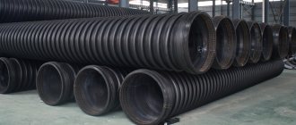
A modern replacement for concrete is polymers. These are durable and sealed corrugated tanks. Sometimes a piece of large diameter plastic pipe is used. To prevent it from deforming, it is protected with a metal mesh.
Cast iron is durable and is used for manholes in multi-storey buildings. Application for private sewerage is complicated by the complexity of installation due to its heavy weight.
Installation of concrete well rings
All work related to the installation of concrete structures must be performed with special equipment. Likewise, the installation of reinforced concrete rings for a well should be carried out using mobile cranes. Work order:
- Additionally, rubber inserts and concrete mortar are also used, which help to more reliably seal the structure and thereby increase its service life.
- The installation process itself depends on what types have been selected. If the walls have a bottom, then they are the first to be laid and only then the subsequent ones are placed on them.
Tongue-and-groove structures shorten the construction process, as they have their own specific fastenings and are quite firmly fastened together. And if their joints are coated with concrete mortar, the structure will last for more than fifty years.
Types of well rings
Well rings can be made of two materials:
- Concrete.
- PVC.
Peculiarities:
- Both have excellent properties and characteristics. They are widely used for the construction of water supply wells.
- With them, the process of constructing a structure is quite simple and all actions are completed very quickly.
Types of concrete rings
The ring for a concrete well is made from:
- Concrete mortar.
- Fittings.
- Various additives that increase its strength and environmental friendliness.
At the moment there are several types that are used for arrangement:
- Supporting.
- Wall.
- Additional ones.
- Castle ones.
- With a bottom.
- Tongue-crested.
More details:
- Support rings for wells are needed if a hatch will be constructed in the future. They are installed in front of the floor slab and can ensure reliable fastening of the hatch.
- Wall rings for wells are ordinary ones, which are installed on top of each other during the construction of the well. All joints must be filled with concrete mortar to ensure their reliable fastening.
In their design, additional rings for wells are the same as wall rings, only they have non-standard sizes. They are used to provide the required depth. They are installed at the very beginning of the wells below and the wall ones are already attached to them.
- Castle wells are very similar to ordinary concrete wells. Their main difference is that they have a special lock. They are also called tongue-and-groove. In addition to the lock on the upper part, there are special ridges on the lower part. The design, which is assembled from this type of rings, is distinguished by its strength.
- There are also certain holes that are filled with concrete during installation. All of them, when securely fastened, are not capable of horizontal shifts. Reinforcement also takes part in their production, which gives them greater strength.
- Rings with a bottom are not particularly complex in their design, since they are made like wall rings, only they are additionally equipped with a bottom. Accordingly, during construction they are laid on the bottom of the structure and serve as a support for it.
- There are also adjustment rings for wells. They are used to increase the depth of the well in the range of 50 cm. This allows you to obtain cleaner water. They are made of reinforced concrete or PVC.
The photo shows all the types that are used in water supply structures.
Classification according to purpose
How is the tray located in the sewer well?
The sewer well is used to organize turns, pipe drops and other elements as part of the sewer system.
In accordance with their purpose, wells are divided into the following types:
- examination rooms;
- flushing;
- storage (cesspool);
- differential;
- control;
- rain;
- special purpose.
Let's take a closer look at each of the listed types.
- Inspection wells are installed in the longest part of the pipeline, as well as when there are level differences due to soil topography and when the system is rotated.
In the photo - a rotary inspection well
Using this structure, you can inspect the pipeline for blockages and, if necessary, clean it.
- The flushing well is installed at the highest point of the network and is used for preventive flushing of the pipeline.
- The volume of a cesspool type sewer is used to collect waste. The installation instructions for this structure are as follows:
- The waste storage tank must be located in the area adjacent to the house.
- The structure must be located more than 10 meters from the water supply and more than 20 meters from the water intake shaft or well.
Cesspool of a sewer well in the process of pumping
- The distance from the cesspool to the house or other residential structures should be 10 meters. This requirement is intended to eliminate the likelihood of flooding and destruction of the foundation of the house and outbuildings in emergency situations.
- The distance from the structure to the fence on the site should be 1 meter or more.
- The calculation of the volume of the sewer well is determined depending on the average waste rate and the depth of groundwater.
- A drop well is used in pipeline sections with a sharp drop in level. The main purpose of the structure is to ensure the release of wastewater flow velocity.
This is how differential sewer wells are designed
The height of a drop-type well is no more than 4 meters. This limitation is explained by the need for a gentle impact of falling water, since falling water from a greater height over many years can lead to the destruction of the entire structure.
- of the control well is similar to its inspection analogue. The only difference is that it is installed at the junction of two or more networks. Also, such designs are relevant when moving from one pipe thickness to another.
- Rain wells are designed to collect wastewater from drainage systems.
Scheme of wastewater disposal in a country house
- A special sewer well is required if the sewer system intersects with main pipelines.
Important: Before going down into the shaft of a water-sewage well, you must make sure that the air pollution is normal and there is no content of potentially dangerous gases. To make measurements as accurate as possible, a gas analyzer for sewer wells is used.
Design features
Welded metal stepladders for sewer wells
The sewer system well consists of three main structural elements:
- bottoms;
- manhole part;
- connecting part.
Important: If the diameter of the pipeline is 30 cm, meter rings for the well are used, at the same time the manhole should not be less than 70 cm. When using pipes of a larger diameter, a standard bottom with a diameter of 1 meter cannot be used. For proper installation, we punch a hole of the required diameter in the bottom.
Not so long ago, wells were built exclusively using brick and concrete. The process was labor-intensive, which negatively affected the cost of the system as a whole. In addition, the structures built in this way were not the most durable and required periodic repairs.
Ineffective technologies have been replaced by industrially manufactured reinforced concrete structures. The cost of sewer systems built using reinforced concrete has become an order of magnitude more affordable, and the service life has increased significantly. And most importantly, the implementation time for sewerage construction has been reduced significantly!
Sewage systems of various configurations and varying degrees of complexity can be assembled from reinforced concrete structural elements. This is largely due to the fact that reinforced concrete products have clear standard values, and the range of such products includes dozens of different modifications from which one can choose one or another option.
Tip: When laying a sewer pipeline, do not make sharp turns. For example, the angle between the inlet and outlet pipes should not be less than 90 ̊. Also, in order to eliminate the possibility of pipeline deformation, the turning radius must be greater than the pipe diameter.
The elements of sewer wells include the following reinforced concrete products:
- additional rings;
- road slab with top position;
- floor slab used in sewer systems with large diameter pipes;
- neck;
- wall ring;
- the bottom is in the form of a solid reinforced concrete slab.
What can wells be like?
At the moment, there are three types of wells that are used in suburban areas:
- Water pumps.
- Observations.
- Sewer.
Functions of water wells
The main function of this design is to provide water to a residential building. may be different, since the aquifer is located differently in each area. As a rule, wells with water supply are mines and various materials are used to equip them inside:
- Wood that is used to line the entire perimeter of the internal walls of the structure.
- Stone (brick or natural agglomerate) that is used in a similar way.
- Rings. Here the choice of such material for arrangement is quite wide.
Current requirements for sewer wells
It is especially important to know that according to SNiP, inspection wells for pipelines with a pipeline size of up to 150 mm are installed every 35 m, and for 200 - every 50 m of direct-flow pipeline sections. In addition, installation of structures is indicated when:
- Rotary changes in the water drainage system;
- When the diameter of the pipeline changes or there is a slope;
- Where additional branches enter.
Documents regulating the requirements: for reinforced concrete products - GOST 2080-90, for polymer structures - GOST-R No. 0260760. Manufacturers offer specifications for plastic structures, supplementing existing regulations.
Stone structures can be made from prefabricated, monolithic concrete, reinforced concrete mixtures, and bricks. The filter structures are made of rubble stone. For the manufacture of polymer structures, it is permissible to use polyvinyl chloride (PVC), polypropylene (PP), and polyethylene of the required density (PE).
Important! Models can be made from a combination of materials.
Sewer stairs KL-1
We produce ladders for sewer wells of any size at the customer's request.
| Type of stairs | Length (m) | Price |
| KL-1-2.0 | 2,0 | 2430 |
| KL-1-2.5 | 2,5 | 2955 |
| KL-1-3.0 | 3,0 | 3480 |
| KL-1-3.5 | 3,5 | 4000 |
| KL-1-4.0 | 4,0 | 4530 |
| KL-1-4.5 | 4,5 | 5000 |
| KL-1-5.0 | 5,0 | 5570 |
| KL-1-5.5 | 5,5 | 6110 |
| KL-1-6.0 | 6,0 | 6650 |
The price list shows average prices including VAT and delivery.
When building modern drinking wells, special reinforced concrete rings are used. To prevent the work from being delayed, they are immediately brought to the site and unloaded near the place chosen for digging the well. The exact quantity that will be required to construct the mine becomes known only after the aquifer has been found.
Sewer wells - SNiP, design and installation diagrams
The technology for arranging sewer wells has been worked out to the smallest detail and documented. Construction regulations prescribe a basic series of regulations that the work carried out must comply with. In particular, SNiP has number 2.04.03-85 and is called “Sewerage. External networks and structures.” The document regulates the locations of different types of structures, dimensions and requirements for the structures being erected.
Regardless of the purpose, private or public use, the installation of sewer wells must be carried out in accordance with the rules and requirements. For example, an inspection object must be located in front of the entrance of the local sewerage system to the centralized sewer, outside the red building line.