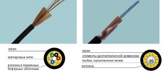
Description of the theodolite itself
With its help, fairly accurate measurements of horizontal and vertical angular quantities are made.
Externally, it is made in the form of a U-shaped optical device located on a rotating platform. The device platform is made in the shape of a circle, on which angular divisions are marked. In addition to the horizontal one, there is also a vertical circle with the same angular divisions. To measure range, it is equipped with various rangefinders. Modern theodolites have electronic components that improve the accuracy of measurements.
Theodolite and its components
The design of a theodolite is based on the laws of optics, mechanics, and electronics.
Theodolite device 2t30
The theodolite diagram includes the following main parts:
- the optical part of the device is a telescope;
- two perpendicularly located circles (one vertical, the other horizontal);
- Tragger systems (allowing you to remain in a stable state for a long time);
- built-in microscope (measurement method can be line or scale);
- a special rotary ruler (called an alidade);
- fixing and guiding screws;
- adjustable tripod (with its help, installation on the ground and preparation of the device for operation).
Main components of theodolite
Despite the variety of such measuring devices, the structure of the theodolite remains the same:
- sighting tube, which is fixed between two vertical columns;
- reading devices (made in the form of circles with measuring scales marked along the perimeter);
- in mechanical devices, reading devices have a bar or scale system;
- optical plummet (called “pivot”);
- adjusting device (called “cremariere”);
- All of the listed device systems are located on a tripod.
Electronic theodolite
The theodolite cremarier allows you to solve the following range of problems:
- rigidly fix the position of the optical sighting device (this is necessary for accurately taking readings from the dial);
- measure the distance to the selected object;
- make accurate sighting of objects regardless of range;
- adjust the focusing lens;
- bring the main axis of the entire apparatus into a strictly vertical position;
- contributes to obtaining the so-called “virtual image”.
Reading devices
These devices allow you to count the divisions of the device dial up to the permitted fractions. They are divided into three categories: line, scale, micrometers. The angular scale can be located on a circle. In this case, it is called a goniometric circle or limb. Each of them has its own angular value for dividing the limb. In real instruments, the division accuracy varies in the range from one degree to five arcminutes. The size of the dial (diameter) is determined by the design of the theodolite. The size can vary from 72 mm to 270 mm.
Reading devices
The following can be used as a reference index: a single stroke, a double stroke, which is called a bisector, a zero stroke, a stroke of the main scale of the existing dial.
The simplest measuring device is a vernier.
Levels
They are necessary for precise adjustment of the theodolite relative to its vertical guide. They are used to measure small angles in the vertical plane. Any level consists of the following elements:
- a small glass flask containing a special liquid inside;
- housings that protect the flask from mechanical influences.
They are made round or cylindrical.
Flasks of cylindrical levels are made from special glass, which contains molybdenum. The liquid inside the flask is ethyl alcohol. Indelible strokes are applied to its surface at intervals of 2 mm. The minimum angle of inclination in any direction at which bubble displacement is observed is called the maximum sensitivity value.
Round level
Cylindrical level
Circles are drawn on the surface of the glass of cylindrical levels from the center to the edge with the same interval.
Theodolite device
All groups of theodolites have practically the same basic design. It includes the following main parts:
- a base with a stand on which the rotating part of the tool is fixed;
- the actual rotating part, consisting of a lower horizontal circle with a cylindrical level, two vertical columns (one with a vertical circle and a tilt compensator), a telescope and a reading microscope.
A more detailed structure is depicted in detail in Fig. 1. Appearance of the T30 optical theodolite. Each individual node has its own purpose and is interconnected by geometric and structural connections.
A wide metal platform (1) is used to mount the instrument on a tripod using a mounting screw.
The horizontal circle (2) in the lower part of the device body consists of a reading mechanism (alidade) with a fastening screw (3), a micrometer guidance screw (4), and a cylindrical ampoule of a horizontal level (5) for rotation through 360º.
The vertical circle (19), which is a single unit with the vertical stand (12), contains a reading device with a backlight mirror (16) and a groove for fixing the compass (18). Its purpose is to measure vertical angles (inclination).
The second vertical stand is equipped with a fixing screw (8), a ratchet (7) for focusing the image, and a vertical circle micrometer screw (6) for precise alignment of the telescope.
The telescope, structurally fixed between two posts, includes a viewfinder (9), an eyepiece in the form of a lens for viewing the image in the field of view of the tube (10), an eyepiece of the reference microscope (11) and a lens (17). It is designed for aiming at sighting targets.
The design of the tribrach (21), containing lifting screws (15), contains a dial in the form of a round ring with marked divisions on its scale (13), its fastening (14) and micrometer (20) screws.
Fig. 1. Appearance of the T30 optical theodolite
Optical theodolites, whose main purpose is to measure angles, represent a design scheme consisting of three systems:
- measuring;
- guidance;
- orientation.
The orientation system includes geometric mutual connections of vertical and horizontal positions between the axes of rotation of the tool, levels and plumb lines.
The guidance system includes rotating mechanisms, geometry and telescope optics.
The measurement system represents vertical and horizontal circles with scales on both dials, alidade reading devices and an optical microscope.
Types of theodolites
Modern designs are distinguished by a variety of design features. The classification of devices is based on the following characteristics:
- operating principle;
- acceptable accuracy of measurements (types of theodolites);
- designs;
- species features.
According to the principle of operation, the devices are produced:
- mechanical;
- optical (reading is based on the optical system);
- digital (counting is done using electronic devices);
- laser (based on the principle of laser meters).
Types of theodolites:
- high precision;
- accurate;
- technical.
Digital theodolite
Structurally, the devices are made in two variants: repeating, non-repetitive.
There are types of theodolites:
- traditional;
- with built-in compensator;
- autocallimation;
- direct vision;
- mine surveyor;
- electronic.
Today the following system for designating such devices has been adopted. The letters indicate the relationship according to the accepted classification:
- “T” is the name of the device, that is, theodolite. The following letters indicate the relationship to a particular class.
- M is the so-called surveyor's theodolite. They are used in mines, tunnels, caves, and mountain passages.
- K - indicates the presence of a special compensator that completely replaces the levels.
- P – equipping the instrument with a direct vision telescope (the image is not inverted).
- A – built-in autocallimator.
- E – electronic theodolites.
Optical surveying theodolite 2T30M
High-precision measurements allow making angular measurements with an acceptable error in the range of 0.5 arc seconds, but not more than one arc second. The second type (precision) instruments make such measurements with an accuracy of two to fifteen arc seconds. The accuracy of technical units is in the range from twenty to sixty arc seconds.
Principle of horizontal angle measurement
The basic principle of angle measurement is to determine the degree value between the directions of two selected objects. Before starting measurements, it is necessary to carry out preparatory operations, including leveling.
Next, the zero mark of the goniometer circle should be positioned in the direction of the axis of the measured angle. After this, the angle is measured on the scale of the horizontal circle.
The most common measurement methods are:
- method of successive repetitions;
- circular method.
The sequence of implementation of the first method is as follows. Preparation and installation at the specified location. The optical sight is first aimed at one selected object. It is then directed in the direction of another object. Before this, a preliminary visual guidance is carried out. By using the focusing screw while simultaneously adjusting the diopter ring, you can accurately target each object. The accuracy of the operation is assessed using vertical threads. Having fixed the direction to the first object, read the readings marked on the horizontal circle. Next, loosen the fastening screw and change the direction of the optical device to the second object. Repeat the data fixation operation. Readings are taken from it and recorded.
The second method is suitable for measuring horizontal angles from one point. Using an alidade, the device is oriented towards the first selected object and the dial is set to zero. Next, move the telescope in the selected direction (clockwise). I read the readings according to the horizontal circle. The final result is calculated taking into account the established error of a particular device.
Necessary verifications
To ensure proper operation of the device and achieve the required measurement accuracy, before starting field work, compliance with the necessary conditions is monitored - the so-called theodolite verification. The correct order of their implementation is necessary to identify and eliminate deviations in the relative position of all the main axes of the theodolite, which is called the geometric conditions of the device.
Reliability of fastening
Working with the tool begins with bringing the stand with a tripod into a stable position and securing it to the tripods using a set screw. Checking the fulfillment of this condition is carried out by lightly turning the stand from side to side and simultaneously observing any clearly visible point on the ground through the crosshairs of the threads. The condition is considered fulfilled if the position of the selected point does not change relative to the crosshairs.
The fastening of the theodolite to the tripod should be quite reliable, but you should not overtighten the mounting screw. Tight rotation of screw devices leads to their rapid wear and failure. Before using the device, check and, if necessary, tighten the screws securing the tips on the legs of the tripod and on the hinges of its head. The lifting screws are fixed in a stable position, and the play between them and the device stand is eliminated.
Level setting
The OB of the alidade must be perpendicular to the axis of the cylindrical level on the horizontal circle. Checking the fulfillment of this condition begins with installing the theodolite in the working position and rotating the alidade to a place where the cylindrical level is approximately parallel to both lifting screw mechanisms. Then, by rotating the screws, the level bubble is brought exactly to the zero point. The position of the bubble is checked again after the alidade is rotated 180°. The condition is met when the bubble remains at the zero point.
If the position of the level bubble has changed by one or more divisions, then adjustment is made using correction and lifting screws. Using screw mechanisms of the level, the bubble is moved in the direction of the zero point up to half the distance of its displacement, then it is brought to the zero point with lifting screws.
Spotting scope
The correctness of the measurements is ensured only if the OB of this part of the theodolite is perpendicular to the sighting axis. For verification, the theodolite is pointed at a certain fixed point. If the condition is met, the difference in readings along the horizontal circle between the values obtained for the left (L) and right (R) positions of the vertical circle should be 180º. If the sighting axis is not perpendicular to the OB pipe, then the L and P readings will differ from the correct value by the same amount, which is called double collimation error.
It is calculated by the formula 2c = (L - P ± 180°) and should not be higher than the double precision of the instrument. If the permissible error values are exceeded, the deviation angle is eliminated by adjusting the vertical stroke of the mesh threads using side screws. The grid is moved to the right by screwing in the left screw and unscrewing the right screw, and to the left - vice versa.
The axis of rotation of the alidade must be perpendicular to the OB of the telescope, which ensures the verticality of the collimation plane. The verification operation begins with sighting a high point at an inclination angle of 25-30º near the selected object. Then the pipe is moved to a horizontal position, and the place where the central thread of the mesh is located is marked on the wall.
After this, the pipe is moved through the zenith, sighted at the selected point and its projection is marked. The condition is considered met when the images of the first and second projections are within the bisector (the area between two strokes) of the thread grid. If the theodolite does not pass this verification, then the device requires a change in the tilt of the axis, which is carried out in a repair shop.
Filament mesh
The vertical stroke of the reticle threads must be perpendicular to the OB of the telescope. Verification is carried out by pointing the crosshairs at a clearly visible point of a nearby object and then tracking its location in relation to the vertical stroke while turning the pipe with a guiding screw.
The condition is considered fulfilled if the selected point does not move from the stroke. If the condition is not met, the need for adjustment arises.
To do this, after removing the protective cap of the reticle and loosening the eyepiece mounting screws, turn it until the observed point is completely aligned with the vertical line.
Geometric parameters of theodolites
Geometric parameters mean strict adherence to the geometric position of each theodolite element.
These parameters are:
- Position of the cylindrical level (located perpendicular to the axis of the grand rod).
- Direction of the line of rotation (vertical to the line of the main rod itself).
- Orientation of the central axis of the sighting tube (horizontal, regardless of the direction and magnitude of the rotation angle).
- Orientation of the telescope and the main rod (always mutually perpendicular).
Theodolite guidance system
Consists of a telescope and associated micrometer screws for precise targeting of the observation target. The telescope itself consists of a metal body, an optical system consisting of a lens (1) with an eyepiece (2), a reticle (5), a focusing lens (3) with a ratchet (4). The optical diagram of the main part of the guidance device is shown in Fig. 3. Spotting scope.
Fig.3. Spotting scope.
Sighting at distant points is carried out through the eyepiece lens and focusing the image using a screw or ratchet ring that moves the internal focusing lens. When a clear image appears in the lens, precise aiming at the target is performed using a grid of threads, the visibility of which is adjusted by the diopter ring. A line passing invisibly through the centers of the eyepiece and objective is considered the line of sight. The compliance of its position with the design and geometric conditions relative to the axes of other components of the optical device is verified by performing operational tests of the instrument.
Fig.4. The structure of the reticle (a) and the image in the field of view of the eyepiece in the T30 (b), T30M (c) devices.
Instructions for bringing the theodolite into working position
Preparing the device is a very important step before taking measurements.
Centering
The action involves a preliminary selection and subsequent installation of the theodolite exactly above the center of a known geodetic point. This is usually carried out using an optical plummet. In other cases, use a regular construction plumb line.
Leveling
It involves installing a horizontal circle using level readings in a horizontal position.
Leveling theodolite
It is performed after completing an additional check of the alidade level. Adjustment is made using lifting screws.
Focusing
Focusing the device involves setting a clear image. The installation accuracy is assessed by the clarity of the observed filament grid. It is carried out by slowly changing the position of the diopter ring. The movement continues until a clear image of each thread is obtained.
Installation of theodolite for verification
First of all, the measuring device is installed in the working position, and then the adjustment is carried out.
Reticles of theodolites' telescopes.
First, check the centering of the device: the vertical axis must align exactly with the reference point. To do this, the plumb line is secured to the stand with a special hook. The stand must be moved until the reference point and the plumb line are at least approximately aligned. At the same time, you should ensure that the position of the stand is horizontal. If the alignment is only approximate, it is necessary to check the stability of the installation of the device. Only after this they proceed to fine-tuning the theodolite.
The screw located on the frame is loosened, then the device is moved along the stand so that the accuracy of the match is within 2-5 mm. After this, the screw can be tightened again.
The second step is setting the horizon. The vertical axis is aligned using a plumb line. It is placed on a horizontal circle so that it is located between two screws intended for lifting. The level is then adjusted to the zero position, which can be adjusted using the lifting screws.
The alidade is positioned at an angle of 90° to the position it originally occupied. Using the third screw, the zero level is fixed. When adjusting the alidade, you need to make sure that when you turn it, the level remains in the same state. A shift of no more than 1° is allowed. If the value turns out to be greater, then the leveling will have to be repeated.
After adjustment, the alidade adjusts the optics to suit individual vision. The tube is directed to a light-colored area of the surface and, by adjusting the position of the eyepiece, the view of the sight is obtained. By changing the position of the ratchet screw, the sharpness is adjusted. When working with objects located at different distances, sharpness must be adjusted in each specific case.
Theodolite measurement
Measurements of horizontal and vertical angles are carried out using a proven device. Before taking measurements, it is necessary to check the smooth movement of all moving parts of the device. Rotate the device's alidade, screws, and cremarriers. Reducing possible errors is achieved by rotating the alidade in the selected direction. Movements should be smooth without sudden jerks. It is not advisable to carry out reciprocating movements.
Before starting to measure the angle in the horizontal plane, the device is installed vertically above the reference point. Then the necessary preparatory actions are carried out. To get good results, you should repeat these steps several times. This will eliminate possible errors and inaccuracies that could negatively affect the measurement result.
The processes for measuring angles in different planes are fundamentally different. These differences are:
- The horizontal angle is calculated as the arithmetic difference between the measured values. The vertical angle is determined between the plane and the amount of elevation of the telescope.
- The horizontal angle is measured on pre-selected areas of the circle, the vertical angle is measured without any rearrangements.
- The number of methods for determining horizontal angles exceeds this number for vertical angles.
Processing of the measurements taken consists of calculating average values. The result is subtracted from other results. In this way the “reduced direction” is obtained. An assessment of the collimation error is used to confirm the accuracy of the measurements taken. It is obtained on the basis of available passport data on the accuracy of the theodolite.
If you need to obtain more accurate calculations, you can use the methods of probability theory and mathematical statistics. Calculate the mathematical expectation and variance.
Geometric diagram of theodolite
2
Rice. 4.6
During the measurement process, the axis of rotation of the theodolite OO
must be plumb, passing through the center of the scale of the horizontal circle 1 and the vertex of the measured angle 8. The plane of the dial 1 must be horizontal, and the sighting (collimation) plane vertical.
To fulfill these conditions, the axes of the theodolite must occupy the following position:
* cylindrical level axis UU
must be perpendicular to the axis of rotation of the
OO
;
* sighting axis of the pipe VV
must be perpendicular to the horizontal axis of rotation of the
LV
;
non-perpendicularity of the indicated axes is called collimation error
;
* horizontal axis of rotation of the LV
must be perpendicular to the axis of rotation of the
OO device.
Actions that result in checking the fulfillment of the specified geometric conditions are called verifications
theodolite.
Elimination of detected inconsistencies in the relative positions of the axes is called adjustment
(correction).
Checking and adjusting theodolites are described in the Manual /5/.
Vertical circle 2 can be located to the left or right of the pipe. These positions are designated respectively L
and
P.
_
The measurement of horizontal and vertical angles is carried out symmetrically: half with circle L
, and the second half with
circle P. This leads to increased accuracy by eliminating errors introduced by insufficient correspondence of the relative positions of the theodolite axes.
Measuring angles
Before measuring angles, the theodolite is placed in its working position: centered, leveled, and the tube is focused along the eye. At the points between which the angle is measured, sighting targets are installed. When measuring angles with technical theodolites, poles are used as sighting targets; for more precise work, sighting marks are used.
4.4.1. Measuring horizontal angles and directions
The horizontal angle b between the directions to points 1 and 3 is equal to the difference in readings a3
and
a1
along the horizontal circle of the theodolite (Fig. 4.7):
b = a3 – a1.
To eliminate the influence of collimation error and the inclination of the pipe rotation axis, each angle is measured at two positions of the vertical circle - to the left (L) and to the right (R) of the pipe.
The measurement method depends on the number of directions at the vertex of the angle. Most often the number of directions is two, i.e. at the apex one angle is measured. To measure a single angle, a technique consisting of two half-steps is used. In each half-reception, two counts are taken: a3l, a1l
when the vertical circle is located on the left and
а3п, а1п
when the circle is on the right. Having received two angle values from two half-measures, compare them. If the discrepancy does not exceed the tolerance, then the average value of the angle is calculated. Otherwise, one of the half techniques or the entire technique is repeated. The permissible value of the angle deviation in half-receptions depends on the type of theodolite and the purpose of the work and usually should not exceed twice the reading accuracy on the dial (1¢ for theodolite 2T30 and 0.2¢ for theodolite 3T5K).
The method of installing the theodolite in the working position and measuring angles using the method is described in detail in /1, 2, 5/.
If the number of directions at a point is more than two (Fig. 4.8), then they are measured using circular techniques. As in the previous method, the circular technique consists of two half-techniques, one of which is performed with the left and the other with the right position of the vertical circle. One of the directions (with the best visibility) is chosen as the initial direction - the first. The pipe is pointed in all directions in turn. Finish the half-reception by closing the horizon
– by re-pointing the pipe to the first direction. The purpose of closing the horizon is to control the immobility of the limb during the half-reception.
If the horizon D is not closed, i.e. the difference in readings in the first direction at the beginning and end of the half-reception does not exceed the tolerance, then it is distributed with the opposite sign to all directions, but more often the average of the observations in the initial direction is simply calculated.
In the first half-step, the alidade is rotated clockwise, in the second – in the opposite direction in order to reduce the influence of external conditions on the measurement results.
Increased accuracy is achieved by measuring horizontal directions using several techniques. To distribute the readings evenly across the entire dial scale, before each next step, the horizontal circle is shifted by an angle of 180o / n +
d, where
n
is the number of receptions, d is 5¢ or 10¢.
Log processing consists of calculating the average values measured at L
and
P
directions and reducing them to zero by subtracting the average value of the initial direction from each direction. The number of measurement techniques, permissible values of horizon non-closure and directional fluctuations in individual techniques are regulated for each type of theodolite and type of work by instructions /7, 8, 9/. Techniques that do not meet the tolerances are repeated. As a result of processing, a number of equally accurately measured directions is obtained, the difference of any pair of which gives a number of equally accurately measured angles. Below is an example of a measurement log.
Horizontal direction measurement log
using circular techniques
Clause 18
2nd reception
Theodolite 2T5K
| Name of directions | Readings along the horizontal circle LI P | L–R | L+R | Given direction values |
| 45º 12.4¢ 106 28.9 240 48.1 348 31.5 45 12.6 D L =+ 0.2¢ | 225º 11.6¢ 286 27.6 60 46.5 168 30.5 225 11.8 D P = –0.2¢ | +0,8¢ +1,3 +1,6 +1,0 +0,8 | 45º12.1¢ 45 12.0 106 28.2 240 47.3 348 31.0 45 12.2 | 0º 00.0¢ 61 16.1 195 35.2 303 18.9 – |
The accuracy of measuring horizontal directions is affected by instrument and sighting errors, external conditions, and inaccuracy in the centering of the instrument and sighting targets. Their combined influence should not exceed the reading error on the limb.
4.4.2. Vertical circle of theodolite, measuring inclination angles
The vertical circle of the theodolite is designed in the same way as the horizontal one, tightly fastened to the pipe and rotates with it on the same horizontal axis. Sector digitization of a vertical circle in theodolites 2T30...3T5KP. With such digitization (Fig. 4.9), the reference sign corresponds to the sign of the inclination angle if the vertical circle is located to the left of the pipe (L), and is opposite to the sign of the inclination angle if the circle is located to the right (R).
Example: L = 5º12′; P = – 5º14′.
The angle of inclination is calculated using the formula
v = (L – P)/
2
.
(4.1)
In the example v =
+ 5º13′.
Obviously, with a horizontal position of the sighting axis, the reading along the vertical circle should be equal to zero. Sometimes this condition is not met :
the vertical circle is not placed accurately on the axis of rotation of the pipe, the mesh of threads is not positioned accurately.
Rice. 4.9
Reading along a vertical circle, when the sighting axis is horizontal and the axis of rotation of the device is vertical, is called the zero point
(
MO
). The location of zero is calculated using the formula
MO = (L + P)/
2
.
(4.2)
In the MO
= – 1′.
The place of zero is a constant in magnitude, i.e. systematic, vertical circle error. Like any systematic error, the influence of the zero point can be eliminated in one of three ways:
* by adjustment: on the vertical circle, the pipe guide screw sets a reading equal to the calculated value of the inclination angle, and the center of the thread grid is aligned with the observed point using the vertical adjustment screws of the thread grid or by turning the optical wedge;
* using the correct measurement technique: readings are taken at two positions of the vertical circle - left and right, and the angle of inclination is calculated using formula (4.1);
* by introducing a correction to the results of measurements performed at one position of the vertical circle: from formula (4.2) we obtain
P =
2
MO – L;
L = 2
MO – P;
(4.3)
substituting (4.3) into (4.1), we obtain v = А – MO; v = MO – P.
(4.4)
The error in measuring inclination angles is slightly greater than the error in measuring horizontal angles due to the influence of vertical refraction. Reducing this influence is achieved by measuring forward and reverse angles of inclination.
2
Date added: 2017-06-13; views: 4099; ORDER A WORK WRITING
Find out more:
Correct operation
Compliance with the rules for operating a theodolite will prevent serious errors when taking measurements. These rules include the sequence of actions at various stages of operation of the device:
- during storage;
- in preparation for work;
- during measurements;
- sequence of evaluation of the results obtained;
- procedure for assembling the theodolite after work.
Application of theodolite
Particular attention should be paid to all these rules under special environmental conditions: temperature, humidity, wind strength, lighting. Almost all theodolites have a temperature range permitted for operation from -25 °C to +50 °C of any humidity. However, it should be remembered that too low or high temperatures will affect the accuracy of the readings taken.
Theodolite verification
Like any measuring instrument, the theodolite must be checked periodically. This operation in metrology is called verification. The frequency of verification for each type of theodolites is set individually. Each verification includes a list of the most important parameters that affect the accuracy of measurements.
These device parameters include:
- mechanical (no deformation on the main mechanical parts, integrity of measurement scales, reliability of threaded connections, absence of corrosion elements);
- characteristics of the device's optical system;
- geometric parameters of measuring elements;
- operability of the cylindrical or circular alidade level;
- the magnitude of the collimation error;
- equal length of all tripod elements;
- accuracy of position and focusing of the mesh of threads;
During verification, adjustments are made to device parameters that are outside the tolerance limits.