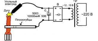
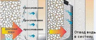
A kerosene cutter for metal is a device designed for quickly cutting steel. It runs on kerosene, gasoline, and diesel fuel on the principle of a burner. Metal cutting becomes possible in the following way: kerosene, which complies with GOST 4753, enters the evaporation refractory chamber under pressure, the evaporating substance enters a special mouthpiece, and oxygen is sent there in parallel.
The substances are mixed in the burner located at the end of the mouthpiece. The result is a high-temperature flame, with the help of which cutting is carried out. The temperature is 2400-2500°C.
Equipment
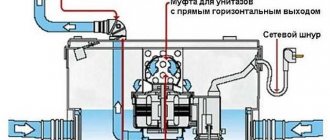
The device includes the following elements: shut-off and starting equipment, cutter, fuel tank, hoses, booster pump, pressure gauge. Since the tool is heavy, it is moved on a special trolley with wheels.
Cutter
The cutter must have an evaporator. It is similar in design to a conventional gas-oxygen installation, but is considered less explosive and safer. The cutter includes a mouthpiece, an injector for mixing oxygen and fuel, a head, an evaporator, and ramp reducers. The flame can be controlled using valves. There is a flywheel for regulation. Fuel is supplied through a hose connected to a tank with fire-resistant filling.
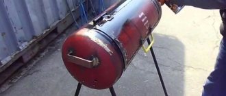
Kerosene burner tank
Typical devices use several types of containers, usually BG-63, a tank-reducer that holds 6.5 liters, or BG-68, designed for a larger volume - 8.5 liters.
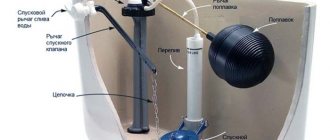
The design includes the following elements:
- Body: its shape is cylindrical. It is welded from several parts. The bottom is made in the shape of a hemisphere, concave.
- The lid usually has a sphere-like design, with holes for the handle for easy movement.
- Shut-off valve.
- A tube with a mesh type filter for collecting the working substance.
- Pressure gauge.
- Pump. It pumps air into the system, creating the necessary pressure.
- The thrust ring is located at the bottom of the body and is used to fill the tank through the fitting. The second outlet is needed for the hose.
The oxygen pressure inside reaches 3 kg/cm2, due to which kerosene enters the hose. The container cannot be filled completely; 30% should always be free. As it is used, some of the substance evaporates and the pressure drops, so the air must be pumped up periodically.
Kerosene burner tank
In typical designs of kerosene cutters (devices produced by the Bobukha Cutter brand are considered especially high-quality), two types of tanks are used: BG-63, with a capacity of 6.5 liters, and BG-68, with a capacity of 8.5 liters. The tank consists of the following elements:
- A cylindrical welded body, the bottom of which has the shape of a concave hemisphere.
- A spherical lid with two sealed holes and a carrying handle.
- Shut-off valve.
- An intake tube with a mesh filter at the end.
- Pressure gauge.
- A manual air pump that creates the necessary pressure to supply kerosene to the hose.
- Thrust ring at the bottom of the housing.
- Two fittings - for connecting a hose, and for filling the tank with kerosene.
When operating the pump, an excess pressure of up to 3 kg/cm2 is created inside the tank body, due to which the kerosene is forced out into the hose. Filling the tank with kerosene should not exceed 70% of its nominal capacity, since part of the energy carrier still evaporates. Despite the careful sealing of the fitting into the tank (welding is used), part of the substance still evaporates during pumping, as a result of which the pressure drops. This circumstance forces the use of a pump to pump kerosene from time to time.
Preparing the tank for use involves thoroughly cleaning it, as well as checking the serviceability of the pump and pressure gauge. Despite the presence of a filter, it is recommended to fill the tank only with pre-filtered kerosene. It is unacceptable to use the tank in an inclined or horizontal state. To comply with fire safety rules and for ease of use, the tank is placed at a distance of no closer than 5 meters from the oxygen cylinder, and no further than 3 meters from the place where the kerosene cutter is used.
Maintenance of the unit consists of periodically cleaning the channels with copper or aluminum needles (steel needles are not recommended).
Operational Features Overview
You can find several models of kerosene cutters on the market. The most common is the RK 02 kerosene cutter - a universal device convenient for use in enterprises. It is suitable for cutting material up to 200 mm, quickly heats up to working condition. The affordable price is also attractive - 2500-3500 rubles.
The second popular model is the KZhG 2 kerosene cutter. It has high safety, as it has a protective unit against backfire. Can be used for a long time without fear of overheating of the burner.
The safety valve contains an additional spring to protect against kickback. Such a device is about 1000 rubles more expensive. Cutting thicker metal up to 300 mm is available. The device can operate in a wider temperature mode and comes complete with replaceable mouthpieces.
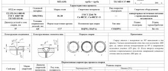
Kerosene cutter, operating principle and technical characteristics
The kerosene cutter is designed for cutting low-carbon steels and instead of flammable gas, liquid fuel is used - kerosene, gasoline, diesel fuel. It is slightly different from an oxygen cutter in some respects, but the principle of operation remains the same. The kerosene cutter can be heated or unheated, and has two mouthpieces (internal and external). When the kerosene is preheated and its vapor enters the asbestos braid of the evaporator located in the mixing chamber, there is a heating nozzle. In the mixing chamber, kerosene vapor is mixed with oxygen, after which it enters the cutter head, in which one part of the mixture is located in the heating nozzle, and the oxygen exits out through the central channel of the cutter head. Oxygen enters the kerosene cutter through a hose through a fitting on the handle of the cutter, and kerosene is also supplied from a special tank under pressure. Passing the tee, the kerosene vapor mixes with oxygen in the mixing chamber and then exits through the outer mouthpiece.
Kerosene cutters for metal are used in two types - with spraying and evaporation. Spray cutters have a special spray device through which liquid fuel is sprayed and then enters the mouthpiece and evaporates there. The evaporation cutter type has an evaporation chamber lined with asbestos. When kerosene enters this chamber, the additional flame vaporizes the liquid kerosene, turning it into kerosene vapor.
An unheated kerosene cutter operating by spray type has some advantages:
- The weight of the cutter is almost half lighter;
- does not have asbestos winding, which allows servicing a kerosene cutter;
- there is no heating flame, so the cutter does not overheat during operation;
- can work at temperatures as low as 400C with a special mouthpiece;
- has high resistance to flame backlash.
An unheated kerosene cutter is a new generation of kerosene cutters, they reach the operating mode in 20 seconds, the kerosene is completely burned, which allows rational use of fuel.
Quick disassembly of the cutter, free access to the parts and assemblies of the cutter, very easy to maintain, unpretentious, simple, reliable, economical, can cut 300mm thick. Such a cutter is the Bobukh cutter “VOGNIK” 181. Another practical kerosene cutter without heating is the RK200 “VOGNIK” 182, which also meets the same requirements as the “VOGNIK” 181. This cutter does not require alignment of the mouthpiece, since the oxygen stream is always adjusted, in the center. Works well in cold temperatures of -250C, minimum output time is 15 seconds, cuts metal from 3 to 200 mm, can pierce metal 50 mm thick. Operates on gasoline with a pressure of 0.5-1.5 kgf/cm2, with an oxygen pressure of 3-8.5 kgf/cm2, simple spare parts, suitable for repair, always available.
An oxygen-kerosene cutter can cut metal, the combustion temperature of which in oxygen is lower than the melting point and the resulting slags must be fluid. The RK2 - 02 cutter is designed for manual separation cutting of low-alloy and carbon steel and can cut a thickness of 200 mm. The combustion of a nozzle on a kerosene cutter can occur from the pressure of the supplied oxygen; it is necessary to comply with the pressure established by the standards, and can also affect the material from which the nozzle is made; copper and bronze are more wear-resistant.
Types of inspection equipment
X-ray television installations, introscopes, are classified into three main categories, in accordance with hygienic requirements:
- Stationary installations with a precisely directed radiation beam. The inspection camera in such devices is closed, and the controlled object is located on a moving belt. Radiation protection is provided due to the special structure of the introscope body. Living objects do not fall within the range of the radiation beam, and therefore such an event seems completely safe for them. High voltage in the X-ray tube is provided only for the duration of the inspection of the inspected object.
- Stationary installations with a wide radiation beam. The inspection chamber in such devices is closed, completely eliminating the possibility of radiation escaping beyond the control zone. The object inside is in a motionless state. Such devices are used for more detailed and thorough checks.
- Mobile X-ray scanners with an open source of radiation. Such devices lack permanent protection. The operation of an X-ray television introscope intended for mobile use must be carried out by an operator wearing a protective suit and wearing special protective equipment. All other observers must leave the inspection area to a safe distance.
Based on design and operational features, X-ray television installations are divided into several groups. So, devices can be distinguished by purpose:
- direct action (fluorographic medical, not related to inspection activities);
- surface probing;
- portable small-sized scanning type;
- scanning X-ray television installations;
- mobile (mobile) systems.
And according to the type of radiation, the following installations are distinguished:
- with combined radiation;
- with absorbed;
- with absent-minded.
All these products are actively used in various fields.
Preparing for operation of a kerosene burner
Preparing a tank for liquid fuel
1. Inspect the tank body 1 (Fig. 1) and make sure there is no damage to fitting 6 with cover 5, manual air pump 2, pressure gauge 3, shut-off valve 4, hose nipple 7 and the body itself.
2. Unscrew cap 5 from fitting 6 and make sure that the tank is clean inside.
3.
Check the operation of the air pump. Why grab the pump handle with your right hand (Fig. 2) and swing it, holding the tank by the upper spherical cover with your left hand and standing on bracket 8 with your right foot (see Fig.
rice. 1). The presence of resistance to the downward movement of the piston indicates that the pump is working properly.
4. Pour kerosene into the tank body. Insert a funnel with felt into the hole in the tank fitting. Stand facing the direction of the wind. Fill the tank at U4 with kerosene into a usable container.
5. Close the fitting hole with the lid.
6. Create a pressure in the tank of 0.15-0.3 MPa using a hand pump.
7. Wash welded and threaded connections with soap foam. Make sure there are no leaks.
Preparing the kerosene cutter
1. Check the presence and serviceability of the kerosene burner parts by external inspection.
2.
Check the alignment of the outer 2 and inner 1 mouthpieces (Fig. 3).
3. Using wrenches, tighten all threaded connections of the kerosene cutter.
4. Check the serviceability of valve 8 for supplying and adjusting kerosene, the heating oxygen valve (not shown in Fig. 3), and the cutting oxygen valve 7 by opening and closing the valves. They should rotate freely, without noticeable effort.
5. Rotate the handwheel // to make sure that it is working properly.
6. Remove the nipple for connecting the oxygen hose 10 from the kerosene burner by unscrewing the union nut 9.
7. Attach the LKO-2-74 safety valve (Fig. 4) to the oxygen fitting (Fig. 3).
8. Attach an oxygen nipple to the L KO valve, and an oxygen hose to the nipple and secure firmly with a clamp.
9. Set the oxygen pressure in the low pressure chamber of the reducer depending on the number of the internal mouthpiece.
10. Open the heating oxygen valve and make sure that oxygen comes out through the gap 15 between the inner and outer mouthpieces and the heating nozzle 14 (see Fig. 3).
11. Open the cutting oxygen valve, check the oxygen output through the central hole 16 of the internal mouthpiece 2 (see Fig. 3).
12. Close the heating oxygen valve, then the cutting oxygen valve.
13. Check the serviceability of the kerosene cutter cart.
14. Connect the tank with a kerosene cutter with a kerosene hose.