How to measure the bend radius of a pipe?
- 1 We carry out calculations for pipe deflection ourselves
- 2 Bending, bending, bending radii of steel, copper and brass pipes depending on the diameter. Smallest radius, smallest free end length required, curved length
- 3 Pipe bending radius: dimensions, materials and features
- 4 Products - Tekhmashholding - group of companies, official website 4.1 To contents
- 4.2 Pipe bends. Pipe bending radii
Profile pipes are common in industrial and private construction. They are used to construct outbuildings, garages, greenhouses, and gazebos. The designs can be either classically rectangular or ornate. Therefore, it is important to correctly calculate the pipe for bending.
This will maintain its shape and ensure the structure’s strength and durability.
Properties of bendable metal
Metal has its own point of resistance, both maximum and minimum.
Maximum load on the structure leads to deformations, unnecessary bends and even breaks. When making calculations, we pay attention to the type of pipe, cross-section, dimensions, density, and general characteristics. Thanks to this data, it is known how the material will behave under the influence of environmental factors.
We take into account that when pressure is applied to the transverse part of the pipe, stress arises even at points distant from the neutral axis. The zone of most shear stress will be the one located near the neutral axis.
During bending, the inner layers in the bent corners are compressed and reduced in size, and the outer layers are stretched and lengthened, but the middle layers retain their original dimensions after the end of the process.
Bend pipes are widely used in daily life
How to make the right calculations
Calculation of a profile pipe for deflection is the determination of the degree of maximum stress at a specific point on the pipe.
Each material has normal stress indicators. They do not affect the product itself. To make the calculations correctly, you must apply a special formula. It is necessary to ensure that the indicators do not exceed the maximum permissible values. According to Hooke's law, the resulting elastic force is directly proportional to the deformation.
When calculating bending, it is also necessary to use the stress formula, which looks like M/W, where M is the bending indicator along the axis on which the force falls, but W is the bending resistance indicator along the same axis.
The pipe bend must be correct and precise
Bending process
Bending creates a certain degree of stress in the metal walls. Tensile stress is obtained in the outer section, and compressive stress in the inner section. Due to these influences, the tilt of the axis changes.
During the bending process, the cross-sectional shape changes at the bent point. As a result, the ring profile takes on an oval shape. A clearer oval shape is visible in the middle of the deflection, but towards the end and beginning the deformation decreases.
For pipes with a cross-section of up to 20 mm, the ovality in the deformed area should not exceed 15%. For pipes with a cross-section of 20 and larger - 12.5%.
Please note that folds may appear in the concave area of thin-walled products. They, in turn, negatively affect the functioning of the system (they reduce the permeability of the working medium, increase the level of hydraulic resistance, and the degree of clogging).
Influence of the final product shape
Successful bending is also associated with the final bending angle α and the minimum permissible bending radius r. The maximum possible values of the marked parameters depend on:
- A type of bending, which can be free (without supporting the middle part of the workpiece on the matrix), or with a calibrating blow, always performed at the end of the working stroke of the stamping equipment;
- Workpiece material and the presence/absence of previous heat treatment, in particular annealing (used for steels supplied in accordance with the requirements of GOST 1050 and GOST 27772);
- Dimensions, tolerances and configuration of the workpiece in its cross section;
- Deformation temperatures.
When bending freely along the bending line of the rod, virtually no transverse deformation occurs. In view of this, at the end of the deformation, the metal has the opportunity to spring back, thereby reducing the required bending angle. The spring properties of a metal are numerically expressed by the springing coefficient, which always increases with increasing content of alloying additives and percentage of carbon. In practice, they use experimental dependences of the springback angle on the ratio r/R, where r is the bending angle, and R is the radius of the original workpiece. For square-shaped rods, instead of the value R, the so-called equivalent radius Re = 1.13√A is taken into account, where A is the side of the square.
The following table can be used to determine the actual springback angle:
In order to prevent cracking in the internal corners of the workpiece during bending, certain bending radius values rmin should be adhered to. For steels, the deformation of which occurs in the delivered state (i.e., without preliminary annealing of rolled products), rmin values are taken according to the following table :
The data given is valid for bending reinforcing bars in a cold state.
Pipe bending radius: dimensions, materials and features
The pipe is simply an irreplaceable invention of man. No technology, construction or comfortable living can do without it. Pipes carry water and gas into our home, while removing all unnecessary waste. In production, they are also integral elements for full functioning. But when using pipes, simple straight laying is not always enough.
They have twists and turns. All this is done in order to position them as comfortably as possible for the consumer and create communications with all amenities. Special devices are used to bend pipes, and this can even be done manually. The method used depends on the material and diameter. Let's consider what the bending radius of pipes is, and all the features of this process.
Free bending
Provides flexibility, but has some limitations in accuracy.
Main features:
- The traverse, using a punch, presses the sheet to the selected depth along the Y axis into the groove of the matrix.
- The sheet remains “in the air” and does not come into contact with the walls of the matrix.
- This means that the bending angle is determined by the position of the Y axis and not by the geometry of the bending tool.
The Y-axis adjustment accuracy on modern presses is 0.01 mm. What bending angle corresponds to a certain Y-axis position? It's hard to say because you have to find the correct Y-axis position for each angle. Differences in the position of the Y axis can be caused by the adjustment of the lowering stroke of the crosshead, material properties (thickness, tensile strength, work hardening) or the condition of the bending tool.
Various factors are important to determine the minimum bend radius, e.g.
Therefore, there is a risk of the workpiece breaking.
Each material that will work also has its own conversion factor. The copper should be bent 5 times. In this case, the minimum radius is equal to the corresponding sheet thickness. Because the tensile strength of harder steels is lower than that of softer steels, the minimum bending radius of high-strength materials is also greater than that of lower-strength steels. Although test bending is performed to determine a truly accurate minimum bend radius. The table below shows the deviation of the bending angle from 90° at various Y-axis deviations.
| a° /V mm | 1° | 1,5° | 2° | 2,5° | 3° | 3,5° | 4° | 4,5° | 5° |
| 4 | 0,022 | 0,033 | 0,044 | 0,055 | 0,066 | 0,077 | 0,088 | 0,099 | 0,11 |
| 6 | 0,033 | 0,049 | 0,065 | 0,081 | 0,097 | 0,113 | 0,129 | 0,145 | 0,161 |
| 8 | 0,044 | 0,066 | 0,088 | 0,110 | 0,132 | 0,154 | 0,176 | 0,198 | 0,220 |
| 10 | 0,055 | 0,082 | 0,110 | 0,137 | 0,165 | 0,192 | 0,220 | 0,247 | 0,275 |
| 12 | 0,066 | 0,099 | 0,132 | 0,165 | 0,198 | 0,231 | 0,264 | 0,297 | 0,330 |
| 16 | 0,088 | 0,132 | 0,176 | 0,220 | 0,264 | 0,308 | 0,352 | 0,396 | 0,440 |
| 20 | 0,111 | 0,166 | 0,222 | 0,277 | 0,333 | 0,388 | 0,444 | 0,499 | 0,555 |
| 25 | 0,138 | 0,207 | 0,276 | 0,345 | 0,414 | 0,483 | 0,552 | 0,621 | 0,690 |
| 30 | 0,166 | 0,249 | 0,332 | 0,415 | 0,498 | 0,581 | 0,664 | 0,747 | 0,830 |
| 45 | 0,250 | 0,375 | 0,500 | 0,625 | 0,750 | 0,875 | 1,000 | 1,125 | 1,250 |
| 55 | 0,305 | 0,457 | 0,610 | 0,762 | 0,915 | 1,067 | 1,220 | 1,372 | 1,525 |
| 80 | 0,444 | 0,666 | 0,888 | 1,110 | 1,332 | 1,554 | 1,776 | 1,998 | 2,220 |
| 100 | 0,555 | 0,832 | 1,110 | 1,387 | 1,665 | 1,942 | 2,220 | 2,497 | 2,775 |
Advantages of free bending:
Rolling direction effect
The values obtained in this way are stored in tables that must be accessible to everyone involved in the operation. Another important factor is the direction of rolling or grain. The stretching of the material during rolling creates the microstructure of the fibrous material. The fiber elongation is always set in the rolling direction. If the sheet or plate is bent longitudinally in the rolling direction, the material may tear. Therefore, the minimum bend radius must be larger. Therefore, bending in the rolling direction is a better option and provides a smaller minimum bend radius.
- High flexibility: Without changing bending tools, you can achieve any bending angle between the V-die opening angle (e.g. 86° or 28°) and 180°.
- Lower tool costs.
- Compared to calibration, less bending force is required.
- You can “play” with force: greater opening of the matrix means less bending force. If you double the width of the groove, you only need half the force. This means you can bend thicker material at a larger opening with the same amount of force.
- Less investment as a press with less force is needed.
All this, however, is theoretical. In practice, you can spend the money saved on purchasing a lower force press that allows you to take full advantage of air bending on additional equipment, such as additional backgauge axles or manipulators.
Bend radii and bend radius
On these press brakes we can use radial dies to bend high precision inner radii.
These materials are very heavy but tend to break if the inner radii are too small. With our radii and dies, we ensure that materials are bent optimally according to their specific properties without losing their stability. Before the radius can be bent in metal sheets or plates, the minimum bending radius must be known. Minimum bending radii depend on the type of material and sheet thickness. Predefined radii are required for many applications. Whether they are required for visual or design purposes. With our radius tools we can produce internal radii with an accuracy of 5mm. We achieve larger radii by repeatedly bending or bending the segment.
Disadvantages of air bending:
- Less precise bending angles for thin material.
- Differences in material quality affect repeatability.
- Not applicable for specific bending operations.
Advice:
- It is advisable to use air bending for sheets with a thickness of over 1.25 mm; For sheet thickness of 1 mm or less, it is recommended to use calibration.
- The smallest internal bending radius must be greater than the sheet thickness. If the inner radius must be equal to the sheet thickness, it is recommended to use the calibration method. An internal radius less than the sheet thickness is permissible only on soft, easily deformable material, such as copper.
- A large radius can be achieved by air bending by using stepwise movement of the backgauge. If a large radius must be of high quality, only the special tool calibration method is recommended.
What effort?
Due to the different material properties and the effects of plastic deformation in the bending zone, the required force can only be determined approximately. We offer you 3 practical ways:
If a workpiece is to be bent at a certain angle, it must be bent beyond that angle because the workpiece recedes slightly after bending. This becomes critical if the metal sheet must be bent to its minimum bend radius, since the spring back means that the bend radius must be less than the minimum bend radius. For this reason, the actual minimum bend radius must always be greater than the theoretical possible radius.
The bending radius is the radius measured after the bending process on the inside of the bending part. The strength of the material decreases as a result of bending. The larger the bending radius, the lower the risk of fracture and the lower the reduction in strength, the smaller the bending radius, the lower the thickness of the material at the bending point of the workpiece. Minimum bending radius is the smallest possible bending radius of the material without destroying the workpiece.
Table
In each catalog and on each press you can find a table showing the required force (P) in kN per 1000 mm of bending length (L) depending on:
- sheet thickness (S) in mm
- tensile strength (Rm) in N/mm2
- V - matrix opening width (V) in mm
- internal radius of bent sheet (Ri) in mm
- minimum height of folded shelf (B) in mm
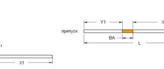
During the bending process, the outer fiber, that is, the outer side of the edge part, is stretched. The inner fiber, the inner side of the edge part, is compressed. Between the outer and inner fibers there is a neutral fiber, which is indicated in green in the image.
To prevent deterioration of quality due to tension and compression, minimum bending requirements must be met. If this value is exceeded, cracks form on the outside, crimps inside and changes in the cross-section in the bending zone. Thus, there is a risk that the workpiece will break.
An example of such a table is the required force to bend 1 meter of sheet in tons. Tensile strength 42-45 kg/mm2. Recommended ratio of parameters and force
Formula
"Rule 8"
When bending low-carbon steel, the width of the matrix opening should be 8 times greater than the thickness of the sheet (V=8*S), then P=8xS, where P is expressed in tons (for example: for a thickness of 2 mm, the matrix opening \/=2x8=16 mm means that you need 16 tons/m)
Bending force and length
The length of the bend is proportional to the force, i.e. the force reaches 100% only with a bend length of 100%. For example:
Advice:
If the material is rusty or not lubricated, 10-15% should be added to the bending force.
Sheet thickness (S)
DIN allows a significant deviation from the nominal sheet thickness (for example, for a sheet thickness of 5 mm, the norm ranges between 4.7 and 6.5 mm). Therefore, you only need to calculate the force for the actual thickness you measured or for the maximum specification value.
Tensile Strength (Rm)
Here too, tolerances are significant and can have a major impact when calculating the required bending force. For example: St 37-2: 340-510 N/mm2 St 52-3: 510-680 N/mm2
Advice:
Don't skimp on bending force! The tensile strength is proportional to the bending force and cannot be adjusted when you need it! Actual thickness and tensile strength are important factors when selecting the right machine with the right force rating.
V—matrix expansion
As a rule of thumb, the opening of the V-shaped matrix should be eight times the sheet thickness S up to S=6 mm: V=8xS For greater sheet thickness it is necessary: V=10xS or V=12xS
The opening of a V-shaped die is inversely proportional to the required force: a larger opening means less bending force, but a larger inner radius; smaller opening means more force but smaller inner radius.
Inner bending radius (Ri)
When using the air bending method, most of the material is subject to elastic deformation. After bending, the material returns to its original state without residual deformation (“reverse springback”). In a narrow region around the point of application of the force, the material undergoes plastic deformation and remains in this state forever after bending. The greater the plastic deformation, the stronger the material becomes. We call this “strain hardening.”
Internal bending radius (Ri) When using the air bending method, most of the material is subject to elastic deformation. After bending, the material returns to its original state without residual deformation (“reverse springback”).
The so-called “natural internal bending radius” depends on the sheet thickness and die opening. It is always greater than the sheet thickness and does not depend on the punch radius.
To determine the natural inner radius we can use the following formula: Ri = 5 x V /32 In the case of V=8xS, we can say Ri=Sx1.25
The soft and easily deformable metal allows for a smaller internal radius. If the radius is too small, the material may wrinkle on the inside and crack on the outside of the bend.
Advice:
If you need a small inside radius, bend at slow speed and against the grain.
Minimum shelf (B):
To avoid the flange falling into the die groove, the following minimum flange width must be observed:
Elastic deformation
Part of the elastically deformed material will “spring back” after the bending force is removed. How many degrees? This is a relevant question, because only the actually obtained bending angle is important, and not the theoretically calculated one. Most materials exhibit fairly constant elastic deformation. This means that a material of the same thickness and with the same tensile strength will spring back by the same amount at the same bending angle.
Elastic deformation depends on:
- bending angle: the smaller the bending angle, the greater the elastic deformation;
- material thickness: the thicker the material, the less elastic deformation;
- tensile strength: the higher the tensile strength, the greater the elastic deformation;
- fiber directions: elastic deformation is different when bending along or across the fibers.
Let us demonstrate what was said above for the tensile strength measured under the condition V = 8xS:
All bending tool manufacturers take elastic deformation into account when offering free bending tools (eg an opening angle of 85° or 86° for free bends from 90° to 180°).
51 Minimum bending radius R of unequal-flange steel with the smaller flange inward, mm
Material - steel St3
| Shelf thickness, mm | Profile number | |||||||
| 3,2/2 | 4,5/2,8 | 5/3,2 | 6,3/4 | 7.5/5 | 8/5 | 9/5,6 | 10/6,3 | |
| 4 | 120 | 170 | 195 | — | — | — | — | — |
| 5 | — | — | — | — | 300 | — | — | — |
| 5,5 | — | — | — | — | — | — | 340 | — |
| 6 | — | — | — | 240 | 300 | 300 | — | 380 |
| 7 | — | — | — | — | — | — | — | 380 |
| 8 | — | — | — | 240 | — | — | 340 | 380 |
| 10 | — | — | — | — | — | — | — | 380 |
51a. Minimum bending radii R of equal flange steel, mm
Material - steel St3
The numerator shows the values of the bending radius of angle steel with the flange facing outwards, and the denominator – with the flange inwards.
| Pack thickness, mm | Profile number | |||||||||||||
| 2 | 2,5 | 3,2 | 3,6 | 4 | 4,5 | 5 | 5,6 | 6,3 | 7 | 7,5 | 8 | 9 | 10 | |
| 3 | 100/120 | 125/150 | — | — | — | — | — | — | — | — | — | — | — | — |
| 4 | — | 125/150 | 160/200 | 180/220 | 200/240 | 221/270 | 250/300 | 280/340 | 315/380 | — | — | — | — | — |
| 4,5 | — | — | — | — | — | — | — | — | — | 350/420 | — | — | — | — |
| 5 | — | — | — | — | — | — | 250/300 | 280/340 | 315/380 | 350/420 | 375/450 | — | ||
| 5,5 | — | — | — | — | — | — | — | — | — | — | — | 400/480 | — | — |
| 6 | — | — | — | — | — | — | — | — | 315/380 | 350/420 | 211/450 | 400/480 | 450/540 | — |
| 6,5 | — | — | — | — | — | — | — | — | — | — | — | — | 500/600 | |
| 7 | — | — | — | — | — | — | — | — | — | 420/350 | 450/375 | 480/400 | 540/450 | — |
| 8 | — | — | — | — | — | — | — | — | — | 480/400 | 540/450 | 600/500 | ||
| 9 | — | — | — | — | — | — | — | — | — | — | 450/375 | — | — | — |
| 10 | — | — | — | — | — | — | — | — | — | — | — | — | — | 600/500 |
| 12 | — | — | — | — | — | — | — | — | — | — | — | — | — | 600/500 |
Calculation of pipe bending radius using a ruler
To carry out the calculations, you need to take two rigid rulers 30 and 50 cm long. Initially, the bending radius of the already bent pipe is measured, which must be repeated on the workpiece. The ruler must be applied to the original pipe and the distance between the ruler and the middle of the pipe must be measured (Fig. 1).
Rice. 1 Measure the width in the original pipe.
Rice. 2. Pipe bending radius.
Using the obtained ruler measurement data, it is necessary to select suitable parameters for the radius and diameter of the arc from tables 1 and 2.
- A – pipe interval (width), mm
- D – arc diameter, mm
- R—bending radius, mm
Table 1. Using a 30 cm ruler
| Interval | 5 | 7,5 | 10 | 12,5 | 15 | 17,5 | 20 | 25 |
| Diameter | 4505 | 3008 | 2260 | 1813 | 1515 | 1303 | 1145 | 925 |
| Radius | 2253 | 1504 | 1130 | 907 | 758 | 652 | 573 | 463 |
| Interval | 30 | 40 | 50 | 60 | 70 | 90 | 100 |
| Diameter | 780 | 603 | 500 | 435 | 391 | 340 | 325 |
| Radius | 390 | 302 | 250 | 218 | 196 | 170 | 163 |
Table 2. Using a 50 cm ruler
| Interval | 5 | 7,5 | 10 | 12,5 | 15 | 17,5 | 20 | 25 | 30 | 40 | 50 |
| Diameter | 12500 | 8341 | 6260 | 5013 | 4182 | 3589 | 3145 | 2525 | 2113 | 1603 | 1300 |
| Radius | 6250 | 4172 | 3130 | 2507 | 2091 | 1795 | 1573 | 1263 | 1057 | 802 | 650 |
| Interval | 60 | 70 | 80 | 90 | 100 | 110 | 130 | 160 | 200 |
| Diameter | 1102 | 963 | 861 | 785 | 725 | 678 | 611 | 550 | 513 |
| radius | 551 | 482 | 432 | 393 | 363 | 339 | 306 | 275 | 257 |
Demand for the technology of “metal bending along a radius”
By bending metal at angles and different radii, the following is obtained:
- elements of curtain facades;
- metal furniture;
- cornices;
- interior details;
- advertising signs, etc.
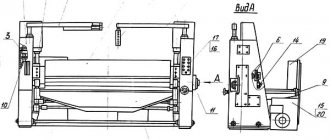
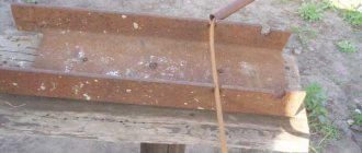
Figure 2 - Radial bending of a channel
The need for radius bending of metal is often encountered in everyday life, during construction and repair. For example, when you need to bend a profile pipe at a certain angle without unnecessary deformations and kinks. It is unlikely that you will be able to do this on your own. High-quality work can only be done with the help of a professional machine. The task of the machines is to perform plastic deformation without damaging the metal. The technology allows you to take into account the characteristics of the workpiece and produce products with different technical data.
K coefficient value
| Minimum bending radius R, mm | Rolled thickness S, mm | ||||||||||
| 0,5 | 1 | 1,5 | 2 | 2,5 | 3 | 4 | 5 | 6 | 8 | 10 | |
| 1 | 0,375 | 0,350 | — | — | — | — | — | — | — | — | — |
| 2 | 0,415 | 0,375 | 0,357 | 0.350 | — | — | — | — | — | — | — |
| 3 | 0,439 | 0,398 | 0,375 | 0,362 | 0,355 | 0,350 | — | — | — | — | — |
| 4 | 0,459 | 0,415 | 0,391 | 0,374 | 0,365 | 0,360 | 0,358 | — | — | — | — |
| 5 | 0,471 | 0,428 | 0,404 | 0,386 | 0,375 | 0,367 | 0,357 | 0,350 | — | — | — |
| 6 | 0,480 | 0,440 | 0,415 | 0,398 | 0,385 | 0,375 | 0,363 | 0,355 | 0,350 | — | — |
| 8 | — | 0,459 | 0,433 | 0,415 | 0,403 | 0,391 | 0,375 | 0,365 | 0,358 | 0,350 | — |
| 10 | 0,500 | 0,470 | 0,447 | 0,429 | 0,416 | 0,405 | 0,387 | 0,375 | 0,366 | 0,356 | 0,350 |
| 12 | — | 0,480 | 0,459 | 0,440 | 0,427 | 0,416 | 0,399 | 0,385 | 0,375 | 0,362 | 0,355 |
| 16 | 0,500 | — | 0,473 | 0,459 | 0,444 | 0,433 | 0,416 | 0,403 | 0,392 | 0,375 | 0,365 |
| 20 | — | 0,500 | — | 0,470 | 0,459 | 0,447 | 0,430 | 0,415 | 0,405 | 0,388 | 0,375 |
| 25 | — | — | 0,500 | — | 0,470 | 0,460 | 0,443 | 0,430 | 0,417 | 0,402 | 0,387 |
| 28 | — | — | — | 0,500 | 0,476 | 0,466 | 0,450 | 0,436 | 0,425 | 0,408 | 0,395 |
| 30 | — | — | — | — | 0,480 | 0,470 | 0,455 | 0,440 | 0,430 | 0,412 | 0,400 |
Minimum bending radius of metals of round and square sections, mm
| Diameter of a circle d or side of a square a | St3 | St5 | Steel 20 | Steel 45 | Steel12Х18Н10Т | L63 | M1, M2 | |||
| R1 | R2 | R1 | R1 | R2 | R1 | R2 | R1 | |||
| 5 | — | — | — | — | — | — | — | — | 2 | — |
| 6 | — | — | — | 2 | — | — | — | — | 2 | 2 |
| 8 | 3 | — | — | 3 | — | 5 | — | 7 | 2 | 2 |
| 10 | 8 | 10 | — | 8 | 10 | 10 | — | 8 | 6 | 6 |
| 12 | 10 | 12 | 13 | 10 | 12 | 13 | — | 10 | 6 | 6 |
| 14 | 10 | 14 | 14 | 10 | 14 | 16 | — | 11 | — | — |
| 16 | 13 | 16 | 16 | 13 | 16 | 16 | 16 | 13 | 10 | 10 |
| 18 | 16 | — | 18 | — | — | 18 | 14 | — | 10 | |
| 20 | 16 | 20 | 20 | 16 | 20 | 20 | 20 | 16 | 13 | 13 |
| 22 | 18 | — | 22 | 18 | — | 22 | 18 | — | 13 | |
| 25 | 20 | 25 | 25 | — | 25 | 25 | 25 | 20 | 16 | 16 |
| 28 | — | — | — | 22 | — | 30 | 22 | — | 16 | |
| 30 | 25 | 30 | 30 | 25 | 30 | 30 | 30 | 24 | 18 | 18 |
51d. Minimum bending radius R of unequal-flange corner steel with the larger flange inward, mm
Material - steel St3
| Shelf thickness, mm | Profile number | |||||||
| 3,2/2 | 4,5/2,8 | 5/3,2 | 6,3/4 | 7,5/5 | 8/5 | 9/5,6 | 10/6,3 | |
| 4 | 195 | 270 | 300 | — | — | — | — | — |
| 5 | — | — | — | — | 450 | — | — | — |
| 5,5 | — | — | — | — | — | — | 545 | — |
| 6 | — | — | — | 380 | 450 | 480 | — | 600 |
| 7 | — | — | — | — | — | — | — | 600 |
| 8 | — | — | — | 380 | — | — | 545 | 600 |
| 10 | — | — | — | — | — | — | — | 600 |
51e. Minimum bending radius of I-beam, mm
(material - VSt3 steel)
| Profile number | 10 | 12 | 14 | 16 | 18 | 20 |
| Minimum bending radius R, mm | 250 | 300 | 350 | 400 | 450 | 500 |
51c. Minimum bending radius R of unequal angle steel with the large flange facing outwards, mm
Material - steel St3
| Shelf thickness, mm | Profile number | |||||||
| 3,2/2 | 4,5/2,8 | 5/3,2 | 6,3/4 | 7,5/5 | 8/5 | 9/5,6 | 10/6,3 | |
| 4 | 160 | 225 | 250 | — | — | — | — | — |
| 5 | — | — | — | — | 375 | — | — | — |
| 5,5 | — | — | — | — | — | — | 450 | — |
| 6 | — | — | — | 315 | 375 | 400 | — | 500 |
| 7 | — | — | — | — | — | — | — | 500 |
| 8 | — | — | — | 315 | — | — | 450 | 500 |
| 10 | — | — | — | — | — | — | — | 500 |