State diagram of iron-carbon alloys
It is convenient to determine the structure and temperature of phase transformations of steel at different temperatures from the phase diagram. In Fig. Figure 1 shows a section of the iron–carbon phase diagram for steel. Each point on the diagram corresponds to its own steel composition and a certain temperature. This diagram is extremely important for the informed choice of thermal conditions for all types of hot forming, including heat treatment of steel.
The AC line is called the liquidus line. Above this line the alloy is in a liquid state. Line AE is the solidus line; it indicates the temperatures corresponding to the end of the primary crystallization of the alloy. Below this line, the alloy is in a solid state, for example with the formation of a body-centered cubic crystal lattice.
The process of secondary crystallization of the alloy in the solid state (for example, the transformation of a body-centered crystal lattice into a volumetric face-centered cubic lattice) ends on the PSK line, called the eutectoid line, or the line of lower critical points A1. Critical points are the temperatures at which structural transformations occur in the steel in the solid state.
The beginning of the process of secondary crystallization of the alloy from the austenite solid solution is determined by the GSE line. The GS line shows the temperature at which ferrite begins to precipitate from austenite. It is also called the line of upper critical points A3. The SE line corresponds to the temperature at which secondary cementite begins to precipitate and the limiting solubility of carbon in austenite. It is also called the line of upper critical points Am. The critical points for cooling are designated Ar, and for heating, Ac.
The regions of existence of solid and liquid phases, as well as various structural components with a schematic representation of the microstructures of steel are shown in the diagram (Fig. 1). According to the diagram, steel containing 0.83% carbon is called eutectoid; it has a pearlite structure.
Rice. 1. Part of the state diagram of iron-carbon steels and temperature ranges for forging and stamping
Steel containing up to 0.83% carbon is called hypoeutectoid; its structure consists of ferrite and pearlite. Hypereutectoid steel contains >0.83% carbon and its structure contains pearlite and secondary cementite.
The most plastic structure is the austenite structure. If there is a two-phase structure in the alloy, its plasticity decreases. Low-carbon and carbon steels at temperatures of 1100...1200 °C have only an austenitic structure. Due to high ductility, a temperature of 1200 °C is taken as the upper limit of the forging temperature range for carbon steel. High-carbon steel at a temperature of 1100 °C has a two-phase structure: austenite + cementite, the latter forming a brittle network along the grain boundaries.
To increase the ductility of steel, it is necessary to crush this cementite network so that the cementite forms individual grains in the metal of the workpiece. At the same time, the hardness and strength of the metal remain high. It is advisable to take the upper limit of forging temperatures for high-carbon steel as ~1100 °C. In this case, forging must be carried out with precautions, taking into account that ductility is reduced due to the two-phase structure.
Using the phase diagram, you can also select the lower limit of forging temperatures, which should lie above the temperatures of phase transformations. It should be noted that low-carbon steels can also be forged with ferrite + austenite structures due to their fairly high ductility.
Hypereutectoid steels have a lower limit of forging temperatures in the austenite + cementite zone. This temperature should be as low as possible to prevent the formation of a cementite network.
The maximum range of forging temperatures becomes narrower with increasing alloying elements in the steel. If for carbon steels it is ~500...600 °C, then for structural alloy steels ~330 °C, for heat-, acid-, and corrosion-resistant steels ~260 °C, for heat-resistant steels ~200 °C, and for heat-resistant alloys ~150 °C.
When establishing the lower limit of forging temperatures, it is necessary to take into account the mass of the forging, the presence or absence of subsequent heat treatment, and the cooling method.
How to choose the right temperature for forging?
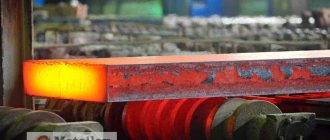
When forging metal at home, you need to take into account that when carbon steel is heated (which is done under the influence of high temperature), the carbon of the top layer burns out to a depth of about 2-4 mm. Due to this, the hardness of the workpiece decreases, which means the hardness of the future product decreases. The steel will significantly lose strength, as well as its ability to harden.
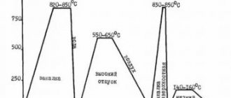
Forging temperature ranges.
Before you start forging, you should make sure that the metal is heated evenly deep down. This condition is very important for the quality of work. It must be borne in mind that if the metal is heated only on the surface, then you should not count on high quality work. It is necessary to take into account that the workpiece acquires uniform plasticity, it must be resistant to deformation, thus it will be much easier to process.
It is necessary to take into account the fact that each grade of steel has its own temperature range, which is best suited for forging. During operation, the workpiece must be periodically warmed up, since its temperature in the open air should not drop.
The effect of heating on the structure and mechanical properties of steel
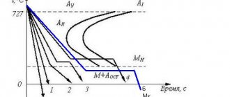
As the heating temperature of a metal increases, the mobility of its atoms increases, causing a number of complex physical and chemical processes to occur. The dynamics and nature of changes in some mechanical properties of the material depending on the heating temperature using low-carbon steel as an example are shown in Fig. 2, from which it can be seen that with an increase in temperature in the region of 200...300 °C, the strength of the metal increases with a simultaneous decrease in ductility. This is the zone of blue brittleness. With a further increase in temperature, the strength of the metal, and therefore the resistance to deformation, continuously decreases. At the same time, the increase in metal ductility in the temperature range 700...800 °C decreases again. This is explained by structural transformations, during which the metal consists of two dissimilar structures characterized by unequal mechanical properties.
When the metal is heated above temperatures of 1100...1200 °C, the growth rate and size of austenite grains sharply increase, which become larger the longer the heating time. This phenomenon is called overheating , and the metal itself with excessively large grains is overheated . The temperature after which intensive steel grain growth and overheating begin is called critical. For carbon steel with a carbon content of up to 0.4% it is 1300 °C and >0.4%
Rice. 2. Change in the mechanical properties of low-carbon steel when heated: 1 – relative elongation δ;
2 – ultimate strength of carbon 1150 °C. A metal with an overheated structure is characterized by reduced plastic properties; during forging, cracks may form, and after forging, the product will have reduced mechanical properties. Overheating is a defect in the heating of the metal. In most cases, it is corrected by subsequent heat treatment (annealing).
When heated to temperatures slightly lower than the melting point [AE curve on the iron–carbon diagram (see Fig. 1)], a sharp decrease in ductility is observed, which is the result of significant grain growth and subsequent burnout of the metal, characterized by oxidation of grain boundaries. The oxides formed along the grain boundaries have a lower melting point than the metal grains, the grain boundaries begin to melt, and a complete loss of ductility of the heated metal occurs. Overburning is an irreparable defect that can only be eliminated by remelting the metal. The burnout temperature for some grades of carbon steels is: for steels 20; 45; U8 and U12 respectively > 1350; 1350; 1200 and 1200 °C.
If the heating time is insufficient, the metal does not have time to heat up evenly over the entire cross-section and has lower ductility in the central zone of the workpiece. Deformation of underheated metal leads to the emergence of significant internal stresses and, when processing a workpiece by forging or stamping, can lead to the formation of cracks in the axial zone of the workpiece.
Heating mode of blanks for forging and stamping
The heating mode of the workpieces determines the conditions necessary for the production of high-quality forgings or stampings. It includes the following main parameters: furnace temperature when loading workpieces, speed or duration of heating of the metal, final heating temperature, holding time at a given temperature, total heating duration. The determining factors when choosing a heating mode are the chemical composition of the metal and the dimensions of the heated workpieces.
The temperature of the furnace working space is set depending on the grade of steel, the size and shape of the heated workpieces. The vast majority of billets made of structural steel, having a diameter or square side of up to 100 mm, are loaded into a furnace at a temperature of 1200...1300 °C. To ensure maximum productivity of the stamping unit (hammer, press, etc.), minimal losses of metal through waste and the formation of scale, as well as a sufficiently high temperature for the start of stamping, the metal is heated at the maximum permissible heating rate (temperature pressure). The heating rate is determined by the increase in the temperature of the workpiece metal in degrees Celsius per unit of time, for example, per minute or hour. It depends primarily on the temperature of the furnace working space, the thermal conductivity of the metal, its heat capacity, density, as well as the cross-sectional area of the workpieces and the method of arrangement of the workpieces in the furnace.
Thermal conductivity is the ability of a substance to conduct heat from more heated parts to less heated parts. The thermal conductivity coefficient shows how much heat (joules) passes in 1 hour through 1 cm2 of a body section with a temperature difference of 1 K at a distance of 1 m. Pure iron has a thermal conductivity coefficient λ = 86 W/(m K), alloy steel 3Х2В8Ф - coefficient
λ = 10.6 W/(m K).
The magnitude of thermal conductivity when heating a metal is important for establishing technological parameters for heating processes of workpieces. Metals and alloys with high thermal conductivity can be heated at a higher speed, since the heat from the surface of the workpieces received from the heating device will be transferred to the metal core intensively and the entire workpiece will warm up quickly enough.
Heat capacity is the amount of heat absorbed by a body when heated by 1 K; the heat capacity of a metal depends on its chemical composition and temperature. The higher the heat capacity of the metal, the longer it takes to equalize the temperature across the cross section of the heated workpiece. With increasing temperature, the heat capacity of carbon steels increases. Alloy additives in steel or alloy reduce thermal conductivity. This circumstance affects the heating time of the workpieces. For example, it is recommended to take the time of holding a workpiece in a furnace from the moment the metal reaches stamping or forging temperature from the following calculation.
1. For structural alloy steels: 1 min for every 4 mm of diameter (thickness) of the workpiece. (The maximum residence time in the furnace at the stamping temperature of workpieces with a diameter or square side of up to 250 mm should not exceed 1...2.5 hours.)
2. For heat-resistant, acid- and corrosion-resistant steels: 1 min for every 3 mm of workpiece diameter. (The maximum residence time in the furnace at the stamping temperature of workpieces with a diameter or square side of up to 250 mm should not exceed 1...2.5 hours.)
3. Workpieces made of heat-resistant steels and alloys at a heating temperature of up to 800...900 °C should be heated more slowly than workpieces made of conventional structural steels. Starting from 800 °C, heating can be accelerated. The total heating time should be increased by 2–3 times compared to structural steels.
4. For uniform heating (holding) of titanium alloys across the cross-section, ~ 40 s per 1 mm of workpiece diameter (thickness) at a temperature of 1000 °C is required and 60 s per 1 mm of workpiece diameter (thickness) at lower temperatures.
5. For aluminum alloys: 1...1.2 min per 1 mm of diameter (thickness) with a diameter (thickness) of heated workpieces up to 100 mm and with a thickness >100 mm - at the rate of 0.8...1.0 min per 1 mm of thickness .
The heat capacity of the metal varies slightly depending on the heating temperature.
The density of a substance is the mass per unit volume. The density of metals significantly affects the heating process. As it increases, the time for equalizing the temperature across the cross section of the workpiece increases.
The general thing is that the higher the temperature in the furnace, the thermal conductivity of the steel and the smaller the cross-section of the heated workpieces and the density of their placement on the furnace floor, the higher the heating rate and the shorter its duration. At the same time, metal waste and decarburization of the workpiece surface are reduced.
If the heating rate is excessively high, a large temperature difference (temperature gradient) occurs across the cross section of the workpiece. The surface of the workpiece heats up faster and to significantly higher temperatures than its core. In this case, in some cases (especially during the initial heating period), significant thermal stresses may arise in the workpiece, the level of which will reach the tensile strength of the steel, and cracks may form. Therefore, a distinction is made between the technically possible heating rate (determined by the capabilities of the heating equipment used) and the permissible rate, determined by the permissible thermal stresses and the level of plasticity of the heated metal.
Cold forging equipment
To engage in cold forging of metal, it is enough to purchase hand tools and a welding machine.
You can also get tools such as:
An important advantage of cold forging is the fact that it does not require much physical effort to create products. Also, working this way does not take up much space.
For a novice blacksmith, it is important to remember that you should follow all the rules of forging metals, properly equip your workshop and have knowledge of basic techniques - the key to the success of a professional.
Cooling of forgings and stampings
The process of cooling forgings or stampings is inherently a thermal operation. Crack formation during cooling is more common than during heating. To prevent cracking and reduce residual stresses, forgings are cooled according to a special regime, which is mainly determined depending on the chemical composition of the steel and the overall dimensions of the forgings. The general thing is that the cooling rate of forgings should not exceed certain values. Traditionally, medium carbon steel forgings are air cooled alone or in racks; forgings made of alloy steels and alloys - in stacks and, depending on overall dimensions, in furnaces according to a special regime.
The methods used for cooling forgings are as follows: in air, in materials with low thermal conductivity (sand, cast iron shavings, slag, slag wool, gravel, etc.), in thermostats, unheated and heated wells, furnaces of various designs.
Terminology[edit | edit code]
There are:
- Free.
- Machine.
- Stamping.
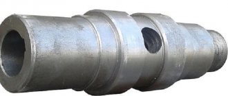
Products and semi-finished products obtained by forging are called “forging”. When forging in dies, the metal is confined on all sides by the walls of the die. When deformed, it takes the shape of this cavity (see Stamping, Rotary forging). With free forging (hand and machine), the metal is not limited at all or limited on one side. In hand forging, the metal or tool is directly impacted with a handbrake, sledgehammer or hammer.