The standards for rejecting steel ropes are very often violated by workers. And this causes undesirable consequences. For example, using a severely damaged sling can lead to an accident and injury (and possibly death) to people. On the other hand, if the significance of the signs of steel rope rejection was greatly exaggerated, then this will result in quite significant unreasonable expenses for the enterprise. This article will be useful to engineers and workers, as well as sailors who deal with cables. Knowledge of steel rope rejection standards will improve labor efficiency and safety.
Basic provisions
The principles of inspection and standards for rejecting steel ropes are specified in a special document numbered 12-97. This will seem strange to many engineers, because usually state standards have been developed for such things. However, this is true. And this document establishes not only the standards for rejecting steel ropes, but also the procedure for their production and operation, installation and maintenance.
According to this manual, metal cables and ropes should be carefully inspected for damage and flaws every ten days. In addition to periodic maintenance, products of this type must be inspected before use (this does not apply only to elevators and other systems in which the cables are hidden).
Cables that operate in particularly hazardous conditions and under heavy loads must be tested at certain intervals using a flaw detector. However, such a device is quite expensive, and only highly qualified engineers who have special courses behind them can work with it.
Rope technical inspection and replacement criteria
In accordance with the ISO 4309 standard, the operational safety of the rope is confirmed by an accurate assessment of the following indicators: - the number of wire breaks and their position; — wear of wires (reduction in rope diameter); — internal and external corrosion; — damage (defects) and wear of the rope.
Broken wire rope
It is necessary to count the number of wire breaks visible on the surface of the rope. In this case, you need to inspect the worn part of the product with special attention. Wire breaks must be monitored in sections of the rope equal to 6 and 30 rope diameters. If the number of wire breaks exceeds the established minimum on at least one of the two specified lengths, the rope must be replaced. Broken wires in a strand usually indicate internal damage to the rope. If the wire breaks, the broken ends should be clearly visible. A rope is considered for rejection if the number of visible broken wires is equal to or greater than the acceptable limit. In 6 and 8-strand ropes, wire breaks occur mostly in the outer layers, while in multi-strand ropes, wire breaks are typical in the inner part. These cliffs are invisible and require special research methods. It is recommended to replace the rope when the broken wires are close to each other at a length of no more than 6d or on the same strand.
Reducing rope diameter
When conducting a technical inspection to replace a steel rope, it is important to pay attention not only to the number of wire breaks. Flattening of the wires due to wear precedes the inevitable breakage. It is necessary to carefully inspect the wires, the diameter of which has visually decreased by approximately 50% compared to the initial state. The diameter of the rope may decrease due to one or a combination of these factors: - internal wear; — external wear due to abrasion of the outer wires; — deterioration of the core (organic/metal) or inner layers of multi-layer torsion-resistant (non-torsion) ropes. The rope must be rejected: - if the decrease in rope diameter exceeds 7% of the nominal rope diameter, only due to external wear; - if the decrease in rope diameter exceeds 3% of the nominal diameter of the non-rotating rope and exceeds 10% for other 6 and 8 strand ropes, due to reasons other than external wear.
Corrosion of ropes
Rope corrosion can be external or internal. External corrosion can be detected visually on the outer surface of the wire rope. Assessing internal corrosion requires specific professional competencies. To open the rope, grippers are used, with the help of which the product is carefully untwisted. In cases with multi-layer ropes and ropes with a metal core, only the outer layer is inspected. The rope must be rejected: - weakening of the wire due to corrosion of the external wires; — confirmation of severe internal corrosion.
Rope deformation
A permanent change from its original shape and orientation is called deformation. The following general changes in shape require immediate rejection of the steel rope: - local violation of the rope; - protrusion of wire, strand or core; - formation of twists or loops; — localized increase in diameter of more than 5% of the actual diameter of the rope; — Localized decreases in rope diameter and lay distance are associated with hard waviness.
Defects in steel rope
Criteria for rope damage and replacement
| Breaks and displacement of wires in two strands of a cross lay rope. The rope must be replaced. |
| Severe wear and a large number of wire breaks in the cross lay rope. Urgent replacement of the rope is required. |
| Wire breaks in one strand and slight wear of the parallel lay rope. It is necessary to remove broken wires and make the rope smooth. |
| Wire breaks in several strands located close to the idler pulley (sometimes pulled by the pulley). The rope must be replaced. |
| Wire breaks in two strands due to bending fatigue and severe localized wear. The rope must be replaced. |
| A birdcage defect in a multi-layer (low-twist) rope caused by excessive rotation around small grooves or too large a deviation angle. Urgent replacement of the rope is required. |
| Protrusion of the steel core, usually caused by lantern-type deformation. Urgent replacement of the rope is required. |
| Loosening of the wires of an individual strand. When examining a section of rope, deformation is observed at regular intervals, usually equal to the lay pitch. This defect must be monitored. |
| A more serious example of the previous defect with protrusion of the internal wires of the strands. Large localized defect caused by impact loads. Urgent replacement of the rope is required. |
| Local increase in the diameter of a parallel lay rope caused by deformation of the metal core under the influence of dynamic loads. The presence of traces of corrosion and severe wear of the outer wires. Urgent replacement of the rope is required. |
| A large knot causing protrusion of the organic core. Urgent replacement of the rope is required. |
| Rope that has been twisted during installation and use, subject to localized wear and strand pulling. The rope must be replaced. |
| Local decrease in rope diameter due to the tendency of external strands to fill the volume of the destroyed organic core. Urgent replacement of the rope is required. |
| Flattening of a section of rope caused by local destruction due to mechanical stress; this defect causes a lack of balance in the strands. There are also wire breaks. The rope must be replaced. |
| Flattening of a section of a multi-strand rope caused by mechanical impact on a large section of rope due to improper unwinding from a winch. The presence of an increased lay pitch of the outer strands with asymmetric stretching under load. The rope must be replaced. |
| Strong bend. The rope must be replaced. |
| The rope coming out of the pulley groove with subsequent deformation, flattening, local wear and multiple wire breaks. The rope must be replaced. |
| The cumulative effect of several factors. Excessive wear of the outer wires, which caused weakening of the wires and “lantern” type deformation; risk of the rope being pushed out of the pulley. Urgent rope replacement required |
Continuation
Wide range of steel rope (cable). There is a system of discounts for regular customers and wholesale buyers. For more detailed information, please contact our specialists.
Delivery within the Russian Federation: Moscow, St. Petersburg, Arkhangelsk, Astrakhan, Barnaul, Belgorod, Bryansk, Vladimir, Volgograd, Vologda, Voronezh, Yekaterinburg, Ivanovo, Izhevsk, Yoshkar-Ola, Kazan, Kaluga, Kirov, Kostroma, Krasnodar, Kurgan, Kursk, Lipetsk, Omsk, Orel, Orenburg, Penza, Perv, Pskov, Rostov-on-Don, Ryazan, Samara, Saransk, Saratov, Sevastopol, Simferopol, Smolensk, Stavropol, Tambov, Tver, Tomsk, Tula, Tyumen, Ulyanovsk, Ufa, Chelyabinsk, Yaroslavl, etc.
>Rejection standards for steel ropes – when is it urgent to change the rope?
Where are the cables most susceptible to wear?
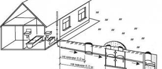
Many years of experience and research into the patterns of wear of steel cables reveal the places most susceptible to wear and destruction. These observations formed the basis for the standards for rejecting steel ropes for lifting structures. In the course of numerous tests and experiments, it was proven that the cables begin to lose their performance qualities and collapse in the places where the ends are fastened, at the ends (overlock), in places of friction with fixed parts of the structure (guides, equalizers, and so on).
Requirements for cables
Rejection standards for steel ropes are valid only if the latter meet industry and production standards.
Cables that are used during rigging, cargo, traction and other work must have a quality certificate from the manufacturer of the appropriate sample. This document contains information about tests carried out on the strength and wear resistance of steel ropes. It is for this reason that ropes that were produced abroad are almost never used in our country. After all, completely different standards apply in Europe and the USA. Theoretically, this is possible, but if you intend to use foreign-made steel ropes, you must obtain documentary evidence of product quality compliance with domestic standards. Such a document is issued by the parent organization for standardization and certification.
If a steel rope does not have documentation confirming compliance with quality standards, then such products cannot be used.
Cables and ropes are supplied from factories to the end user in whole batches. For each such delivery there must be a so-called passport. One batch cannot contain steel ropes of different sizes.
Installation of steel ropes for rejection standards.
Steel ropes used as cargo, boom, cable-stayed, load-bearing, traction, and installation ropes must comply with state standards, have a certificate (certificate) or a copy of the certificate of the manufacturer of the ropes about their testing in accordance with the rules for the design and safe operation of load-lifting cranes. The use of ropes manufactured according to international standards is permitted upon the conclusion of the parent organization or certification body. Ropes that are not provided with a certificate of testing are not allowed to be used.
| Document No. Document No. |
| PEER. 17. 23.01.07. 203 PZ |
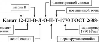
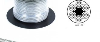
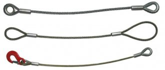
The fastening and arrangement of ropes on cranes must prevent the possibility of them falling off drums or blocks and chafing due to contact with elements of metal structures or ropes of other pulleys. The brand, type and design of the rope must comply with regulatory documents. The choice of steel ropes used as cargo, boom, cable-stayed, load-bearing, traction ropes must be made in accordance with RD 10-33-93, RD 10-231-98, ISO 4308/1, ISO 4308/2 and other regulatory documents. To perform rigging and slinging work, steel ropes are used (Fig. 2.1) with various technical characteristics. Steel ropes are used in mechanisms, pulley blocks, and many mounting devices for equipping lifting masts, chevrons, as well as for the manufacture of slings, cables, braces, etc. A large number of ropes are used to equip cranes operating in industry and construction. Steel ropes are made from high-strength thin steel wire with a diameter of up to 3 mm. The wires are coated with various coatings that increase the service life of the ropes. Ropes made from light-colored (non-galvanized) wire are coated with anti-corrosion lubricant. Ropes made of galvanized wire are used only if this is provided for in the work project (WPP). Ropes come in single and double lay (Fig. 2.2). Single lay ropes are made directly from individual wires. In double laying, individual wires are first twisted into strands, and then a rope is twisted from the finished strands. To give the steel rope flexibility, as well as to retain the lubricant that protects the steel wires of the rope from corrosion, a hemp core is placed in the middle of the rope, in the middle of the strands or between the strands.
| Document No. Document No. |
| PEER. 17. 23.01.07. 203 PZ |
Rice. (08)
Steel ropes: a - cross lay; b - one-sided lay; c - cable design; g - multi-strand (two-layer); d - multi-strand (three-layer); 1 - core; 2 - strand of rope According to the type of lay, steel ropes are: ordinary (unwinding); non-unwinding. To protect against unwinding, dressings of 8...10 turns of soft wire, called a mark, are applied to the ends of the ropes. In addition, depending on the type of lay, ropes are single-sided, cross-laid and combined lay. When laying wire on one side in strands and
| Document No. Document No. |
| PEER. 17. 23.01.07. 203 PZ |
The strands in the rope are twisted in one direction, while in a cross rope - in different directions. With a combined lay, part of the strands has a left and the other has a right lay direction. According to the direction of lay, ropes are: right lay;
left lay. Depending on the number of strands, ropes are: single-strand (or spiral); three-strand; five-strand; six-strand; eight-strand; eighteen-strand.
Rice. (09)
Single (a) and double (b) lay ropes. In installation work, six-strand ropes with a hemp core are more often used.
| Document No. Document No. |
| PEER. 17. 23.01.07. 203 PZ |
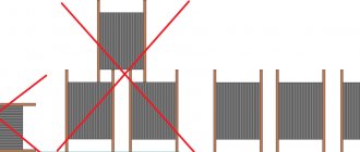
Depending on the type of laying of wires in strands, ropes are: with point contact (TC); with linear touch (LC); with point and linear touch (TLC). During operation of a TK type rope, the wires in contact with each other move relative to each other, which increases their wear and increases the rigidity of the rope. In LK type ropes, point contact of wires between layers in strands is eliminated, which reduces the degree of wear and significantly increases the flexibility of the ropes. Ropes of the LK and TLK types, being the most durable and wear-resistant, are increasingly used in industry. For rigging work and lifting mechanisms, steel ropes of the TK, LK and TLK types are usually used, consisting of six strands, with the number of wires 19, 37 and 61. Ropes with the number of wires in a strand of 19 are rigid, they are used mainly for cables and guy ropes. Ropes with a number of wires in a strand of 37 or more are used for reeving pulley blocks, making slings, and also for other lashing devices. The following ropes are used for installation work: double lay rope type LK design 6x19 (1+9+9) + 1 o.s., i.e. 6x19 (1+9+9) wires and one organic core (GOST 3077-80); double lay rope type TLK design 6×37 (1+6+15+15) + 1 o.s. (GOST 3079-80). Braces, shrouds and rods are made from ropes, which are produced in accordance with GOST 2688-80, GOST 3077-80 and GOST 3070-74; pulley blocks, slings are made from more flexible construction ropes (6×36) + 1 o.s. (GOST 7668-80). Ropes are received from the manufacturer in batches. The batch consists of ropes of the same standard size in one packaging unit. The party is registered with one document - a passport. During operation, the ropes are periodically lubricated. Before lubrication, the surface of the rope is cleaned of dirt and rust with wire brushes and wiped with a cleaning material soaked in kerosene. During long-term storage, the ropes are periodically, at least once a year, inspected and lubricated. Information about ropes in use is entered into a special rope logbook. The ropes are equipped with a metal or wooden tag, which indicates the name or trademark of the manufacturer,
| Document No. Document No. |
| PEER. 17. 23.01.07. 203 PZ |
serial number, symbol, length (m), gross weight of the rope (kg), quality control mark of the manufacturer.
Rejection of ropes Rejection of ropes of load-lifting cranes in operation must be carried out in accordance with the crane operating manual. If there is no corresponding section in the crane operating manual, rejection is carried out in accordance with the recommendations given in the Rules for the Design and Safe Operation of Load-Lifting Cranes. To assess the safety of using ropes, the following criteria are used: the nature and number of wire breaks, including the presence of wire breaks at the end seals, the presence of places where wire breaks are concentrated, the intensity of the increase in the number of wire breaks; strand break; surface and internal wear; surface and internal corrosion; local reduction in rope diameter, including core rupture; reduction in the cross-sectional area of the rope wires (loss of internal cross-section); deformation in the form of waviness, basket-like shape, extrusion of wires and strands, crushing of strands, creases, kinks, etc.; damage due to temperature effects or electrical arcing. An example of determining the number of outer wire breaks is shown in Fig. 2.3. Ropes of cranes intended for moving molten or hot metal, flammable and toxic substances are rejected with half the number of wire breaks.
| Document No. Document No. |
| PEER. 17. 23.01.07. 203 PZ |
Rice. (10) Determination of the number of breaks in the outer wires of a steel rope: 1 - at the inspection site, only one end of the broken wire was detected at the broken wire, the other end is missing (this defect corresponds to one break);
2 - in the inspection section, the broken wire has two ends (this defect corresponds to one break); 3 - at the control site, one of the wires has a double integrity violation (since the integrity violations belong to only one wire, this defect in total corresponds to one break); L is the length of the rope inspection section (taken equal to six or thirty rope diameters). If the rope diameter decreases as a result of surface wear or corrosion by 7% or more compared to the nominal diameter, the rope is subject to rejection even in the absence of visible wire breaks. If the diameter of the rope decreases (by 3% of the nominal diameter for non-rotating ropes and by 10% for other ropes) as a result of damage to the core - internal wear, crumpled, rupture - the rope must be rejected even in the absence of visible wire breaks (Fig. 2.4). Rice. (11) Local reduction in the diameter of the rope at the site of destruction of the organic core. When the original diameter of the outer wires decreases by 40% or more as a result of wear or corrosion, the rope is rejected. Wear or corrosion of wire diameters is determined using a micrometer or other instrument that provides a similar
| Document No. Document No. |
| PEER. 17. 23.01.07. 203 PZ |
accuracy.
If the load is suspended on two ropes, then each is rejected separately, Table (03)
and
| Reduction in wire diameter as a result of surface wear or corrosion, % | 10 | 15 | 20 | 25 | 30 or more |
| Number of wire breaks, % of norms | 85 | 75 | 70 | 60 | 50 |
It is allowed to replace one more worn rope. Rope rejection standards depending on surface wear or corrosion
To assess the condition of internal wires, i.e. To control the loss of the metal part of the cross-section of the rope (loss of internal section) caused by breaks, mechanical wear and corrosion of the wires of the inner layers of the strands, it is necessary to subject the rope along its entire length to flaw detection. When a loss of cross-section of the metal wires is recorded using a flaw detector, reaching 17.5% or more, the rope is rejected. The need to use flaw detection of steel ropes is determined in accordance with the requirements of regulatory documents, depending on the type and purpose of the crane.
Rice. (12) Reduction in the cross-sectional area of the wires (intensive internal corrosion) If one or more broken strands are detected in the rope, the rope to
| Document No. Document No. |
| PEER. 17. 23.01.07. 203 PZ |
no further work is permitted. The waviness of a rope is characterized by the pitch and direction of its spiral. If the directions of the waviness spiral and the rope lay coincide and the steps of the waviness spiral HB and the rope lay Hk are equal, the rope is rejected at dB> l.08dK, where dB is the diameter of the waviness spiral, dK is the nominal diameter of the rope.
Rice. (13) Rope waviness: dB is the diameter of the waviness spiral; dK is the nominal diameter of the rope; Hв is the pitch of the waviness spiral; Hk - rope lay
Rice. (14) Basket deformation
Rice. (15) Core extrusion
| Document No. Document No. |
| PEER. 17. 23.01.07. 203 PZ |
Rice. (16) Extrusion of strands: a - in one strand; b - in several strands
Rice. (17) Local increase in rope diameter
Rice. (18)
Crush rope
Rice. (19) Twisting rope
| Document No. Document No. |
| PEER. 17. 23.01.07. 203 PZ |
Rice. (20) Rope hall
Rice. (21)
| Document No. Document No. |
| PEER. 17. 23.01.07. 203 PZ |
Kink in the rope If the directions of the spiral of waviness and lay of the rope do not coincide and the steps of the spiral of waviness and lay of the rope are unequal or one of the parameters coincides, the rope is subject to rejection at dв > 4/3dK.
The length of the rope section in question should not exceed 25dK. Ropes should not be allowed for further work if: basket-shaped deformation is detected; core extrusion; squeezing out or delamination of strands; local increase in rope diameter; local reduction in rope diameter; crushed areas; twists; creases; kinks; damage due to temperature effects or electrical arcing.
| Document No. Document No. |
| PEER. 17. 23.01.07. 203 PZ |
5) Safety rules when performing loading -
4
Live by the rule: IS THERE NOT MUCH THING IN THE WORLD EXISTING? It is no coincidence that I emphasize that the space in your head is limited, but there is a lot of information around, and that your right...
WHAT AND HOW THEY WRITTEN ABOUT FASHION IN MAGAZINES AT THE BEGINNING OF THE XX CENTURY The first issue of the Apollo magazine for 1909 began, in fact, with a policy statement from the magazine’s editors...
What Causes Trends in Stock and Commodity Markets Freight Train Theory Explained My first 17 years of market research consisted of trying to figure out when...
WHAT IS CONFIDENT BEHAVIOR IN INTERPERSONAL RELATIONSHIPS? Historically, there are three main patterns of differences that exist between...
Didn't find what you were looking for? Use Google search on the site:
What are the ways to detect defects?
The most accessible, simple and cheap way to determine the rejection rate of steel rope slings is the visual method. An external inspection carried out by an experienced specialist using simple auxiliary equipment will allow timely detection of critical damage to the rope strands and take measures to prevent an emergency or accident.
In second place in popularity and effectiveness is the so-called instrumental method of establishing compliance with the standards for rejecting slings made of steel ropes. As research and experimental work have shown, by the nature of straightness and violation of the geometric shape in the cross-section of the cable, one can quite accurately predict its useful life. Not every engineer can do this kind of work. Here you need to have a powerful mathematical apparatus and appropriate instrumental support. Currently, highly specialized software packages have appeared on the market that allow partial automation of routine mathematical calculations. However, the cost of the license is very high, and its acquisition is unlikely to be economically feasible.
The role of the safety factor
This indicator is very important. And its value is numerically equal to the ratio of the breaking force to the cable tension indicator. In accordance with the requirements of the State Labor Safety Inspectorate, norms for strength coefficient values have been established for various ropes. So, for ropes that do not experience significant loads during operation (light operating mode), this value should not fall below 5. For those ropes that operate in difficult conditions and experience enormous loads, the value of the strength coefficient should not fall below 6. Stands out also an intermediate type of cables designed for operation in medium mode. The strength coefficient of such ropes cannot be lower than 5.5.
Checking the strength coefficient can be classified as destructive quality control and rejection, if not of one individual steel rope, then of an entire batch. To conduct such tests, it is necessary to have complex and expensive equipment.
Rejection of traveling ropes
Rejection of traveling ropes is a necessary measure to ensure the safe operation of drilling equipment, since this type of product is one of the so-called “aging” ones, that is, its strength decreases during operation. In today’s article we will look at conservative and modern techniques for conducting flaw detection of traveling ropes, which allow us to timely identify the need for their replacement.
To begin with, let's define that a traveling rope is a special design of a steel rope. In such a rope, strands twisted from steel wires are twisted around the main core. Unfortunately, the service life of such products is quite short, and in the absence of proper attention to the condition of the rope, there is a high probability of an emergency situation with serious risks for both equipment and personnel. That is why rejection of traveling ropes is a necessary condition during drilling operations.
Federal industrial safety standards and regulations suggest visual inspection as a means of monitoring the condition of the tackle channels. The frequency of visual inspection of the condition of the product is determined based on the conditions under which the work is carried out and the nature of the work.
Unfortunately, a visual inspection of the traveling rope does not allow a qualitative assessment of its condition, since it reveals only obvious defects, such as breakage or deformation of the rope strands or wires. To reject the product, the rate of broken wires at a laying pitch of up to 20 mm should be more than 5%, and for a larger pitch – more than 10%. The rope in which a broken strand is found is also rejected. Internal defects (breaks or corrosion) are not detected using this method, which determined the requirement for the development of more modern methods for assessing the condition of the rope.
To achieve high efficiency of flaw detection measures, magnetic devices have been developed, which not only increase the accuracy of the assessment, but also significantly reduce the labor costs for conducting such a study. The principle of operation of such a flaw detector is based on measuring stray fields after magnetization of the rope along the axis. If a visual assessment required up to an hour and a half of a specialist’s time, then the automated operation of a magnetic flaw detector reduced this time to about ten minutes and completely eliminated the need to involve an employee directly in the research process; his participation is only necessary to evaluate the results.
Determination of rope winding pitch
A parameter such as the lay pitch of a cable or rope is very important when considering the issue of rejection. The fact is that the number of breaks in thin fibers is usually calculated over a rope length equal to this pitch.
If there is no experience in carrying out such work, then difficulties may arise. Although in reality everything is quite simple. The pitch will depend on how many strands are in the rope. Next, a mark is made on the surface of one of the strands with a marker or center punch. All that remains is to count the number of strands in the cable one to the right or to the left and put a second mark. The distance between the two marks will be equal to the lay pitch. And it is precisely in this interval that the number of breaks must be counted.
Waviness of ropes
This is a very important feature, and the standards for rejecting steel ropes cannot be silent about it. During active use of the cable, when it is wound onto a drum and unwinded, residual curvatures are formed in it. If the cable is not replaced in time, these distortions increase, and dangerous destructive processes begin in the rope itself.
Therefore, it is important to replace the cable in time. Recommendations have been developed to prevent industrial accidents. The cable must be replaced if the cross-sectional diameter in the spiral area is greater than or equal to 1.08 of the nominal outer diameter of the cable.
Rejection standards due to surface wear and corrosion
Under external influences and loads, steel ropes inevitably undergo surface wear, which can be aggravated by the appearance of corrosion. Signs of surface wear appear in thinning and breaks of the outer wires of the rope strands. In these cases, the steel rope is rejected according to the following standards:
- the number of broken wires in a section of a certain length (not to be confused with the total number of breaks);
- thinning the diameter of the outer wires by 40 percent or more relative to the original value for the new product;
- thinning of the rope diameter due to surface wear by 7% or more relative to the nominal value for a new product.
If corrosion is present, the rejection standards for the permissible number of broken wires are tightened. For example, with surface wear of 10%, a reduction factor of 0.85 is applied to the breakage standards. For wear of 30% or more - 0.5. Rejection standards are established taking into account such circumstances as:
- the number of supporting wires in the outer strands;
- type of rope;
- type of lay;
- nominal diameter;
- design (structure) of the product by the number of wire strands, the presence and type of core.
For example, the nominal diameter of the rope is used to determine the length of the controlled section where breaks are detected. It is taken equal to 6d or 30d. The permissible number of broken wires for each type of rope depends on the type of lay. Rejection standards were approved by Gosgortekhnadzor Resolution No. 98 dated December 31, 1999.
Unconditional standards for the rejection of steel ropes of lifting machines, elevators and other mechanisms
The cable is considered defective if the reduction in the cross-section of the outer wires is forty percent or more. Moreover, the length of the active wear area is not taken into account. Such a cable may not have external signs of wear, but it may break under load.
In addition to the decrease in cross-sectional area, its abnormal increase should also cause concern. The cause of such “swelling” is swelling of the core. According to the rejection standard for crane steel ropes, the critical value for increasing the cross-sectional area is 7% of the nominal area.
Stretching of steel ropes is a natural process that occurs during active use of the cable. However, it should not exceed the established norm. This figure is 5%. Thus, if the inspection reveals an increase in the length of the cable by five percent or more, then the product is considered defective, despite the absence of visible signs of destruction. Moreover, the rejection rate for fine-stranded steel ropes does not differ from the similar rate for heavy-duty cables.
Oil, Gas and Energy
1. Rejection of ropes of lifting machines in operation is carried out in accordance with this appendix. To assess the safety of using ropes, the following criteria are used: a) the nature and number of wire breaks (Fig. 1 - 3), including the presence of wire breaks at the end seals, the presence of places where wire breaks are concentrated, the intensity of the increase in the number of wire breaks; b) strand break; c) surface and internal wear; d) surface and internal corrosion; e) local reduction in rope diameter, including core rupture; f) reduction in the cross-sectional area of the rope wires (loss of internal cross-section); g) deformation in the form of waviness, basket-like shape, extrusion of wires and strands, crushing of strands, creases, kinks, etc.; h) damage due to temperature effects or electric arc discharge. Fig.1. Breaks and displacements of cross lay rope
Rice.
2. Combination of wire breaks with their wear: a - in a cross lay rope; b - in a one-way lay rope Fig. 3. Wire breaks in the area of the leveling block: a - in several strands of the rope: b - in two strands in combination with local wear 2. Rejection of ropes working with steel and cast iron blocks should be carried out according to the number of wire breaks in accordance with the table. 1. Ropes of lifting machines intended for lifting people, as well as transporting molten or hot metal, flammable and toxic substances, are rejected with half the number of wire breaks. Number of wire breaks, in the presence of which double lay ropes working with steel and cast iron blocks are rejected Number of Design Group of classification (mode) of the load-bearing rope mechanism according to ISO and Type GOST for M1, M2, M3 and M4 M5, M6, M7 and M8 wires in external strands according to state lay standards rope cross lay one-sided lay cross-lay one-sided lay on a section length 6d 30d 6d 30d 6d 30d 6d 30d 1 2 3 4 5 6 7 8 9 10 11 12 n50 67(6 /1) 2 4 1 2 4 8 2 4 67(1+6)+17(1+6) LK-O 3066-80 67(1+6)+1о.с. LK-O 3069-80 86(0+6)+9о.с. LK-O 3097-80 51n75 619(9/9/1)* 3 6 2 3 6 12 3 6 619(1+9+9)+1o.s. LK-O 3077-80 619(1+9+9)+ +77(1+6)* LK-O 3081-80 76n100 187(1+6)+1 o. With. LK-O 7681-80 4 8 2 4 8 16 4 8 101n120 819(9/9/1)* 5 10 2 5 10 19 5 10 619(12/6/1) LK- O 3066-80 619(12/6+6F/1) LK-O 3069-80 625FS(12/12/1)* LK-O 3097-80 619(1+6+6/6 )+ +77(1+6) LK-R 14954-80 619(1+6+6/6)+ +1о.с. LK-R 2688-80 625(1+6; 6+12)+1о.с. LK-3 7665-80 625(1+6; 6+12)+77(1+6) LK-3 7667-80 121n140 816(0+5+11)+ + 9о.с. TK 3097-80 6 11 3 6 11 22 6 11 141n160 819(12/6+6F/1) 6 13 3 6 13 26 6 13 819(1+6+6/6)+ +1о.с. LK-R 7670-80 636(14/7+7/7/1)* 7 14 4 7 14 29 7 14 630(0+15+15)+ +7о.с. LK-0 3083-80 161n180 636(1+7+7/7+14)+ +1о.с.* LK-RO 7668-80 636(1+7+7/7+ 14)++77(1+6)* LK-RO 7669-80 631(1+6+6/6+12)+ +1о.с. 8 16 4 8 16 32 8 16 181n200 631(1+6+6/6+12)++77(1+6) 637(1+6+15+15)+ +1о.с. TLK-O 3079-80 201n220 641(16/8+8/8/1)* 9 18 4 9 18 38 9 18 221n240 637(18/12/6/1 ) 1819(1+6+6/6)+ +1о.с. LK-R 3088-80 241n260 10 21 5 10 21 42 10 21 261n280 11 22 6 11 22 45 11 22 281n300 12 24 6 12 24 48 12 24 300n 0, 04n 0.08n 0.02n 0.04n 0.08n 0.16n 0.04n 0.08n Notes: 1. n is the number of supporting wires in the outer strands of the rope; d—rope diameter, mm. 2. Filling wires are not considered load-bearing and therefore are not subject to accounting. In ropes with multiple layers of strands, only the wires of the visible outer layer are counted. In ropes with a steel core, the latter is considered as an internal strand and is not taken into account. 3. The number of breaks should not be confused with the number of broken wire ends, which can be 2 times more. 4. For structural ropes with the diameter of the outer wires in the outer strands exceeding the diameter of the wires in the underlying layers, the design class is lowered and marked with an asterisk. 5. When a rope is operated entirely or partially with blocks made of synthetic material or metal with a synthetic lining, a significant number of wire breaks appear inside the rope before visible signs of wire breaks or intense wear appear on the outer surface of the rope. Such ropes are rejected taking into account the loss of internal cross-section. 6. Blank lines in the column Rope designs according to ISO and state standards mean the absence of rope designs with the appropriate number of wires. When such rope designs appear, as well as for ropes with a total number of wires of more than 300, the number of wire breaks at which the rope is rejected is determined by the formulas given in the bottom line of the table, and the resulting value is rounded up to the nearest whole number. 7. Ropes of lifting machines intended for lifting people, as well as transporting molten or hot metal, flammable or toxic substances, are rejected with half the number of wire breaks. 3. If the diameter of the rope decreases as a result of surface wear (Fig. 4) or corrosion (Fig. 5) by 7% or more compared to the nominal diameter, the rope must be rejected even in the absence of visible wire breaks. Fig.4 Fig.5 Fig. 4. Wear of the outer wires of the cross lay rope: a - small flats on the wires; b - increased length of flats on individual wires; c - lengthening of flats in individual wires with a noticeable decrease in the diameter of the wires; d - flats on all wires, reducing the diameter of the rope ; d - intensive wear of all outer wires of the rope (reduction in wire diameter by 40%) Fig. 5. Surface corrosion of cross lay rope wires: a - initial oxidation of the surface; b - general oxidation of the surface; c - noticeable oxidation; d - strong oxidation; e - intense corrosion When the diameter of the rope decreases as a result of damage to the core, internal wear, collapse, rupture, etc. (by 3% of the nominal diameter for non-rotating ropes and by 10% for other ropes) the rope is subject to rejection even in the absence of visible wire breaks (Fig. 6). Fig.6. Local reduction in the diameter of the rope
at the site of destruction of the organic core. If the rope has surface wear or corrosion of the wires, the number of breaks as a sign of rejection should be reduced in accordance with the data in Table.
2. 1. Rejection of ropes of lifting machines in operation is carried out in accordance with this appendix. To assess the safety of using ropes, the following criteria are used: a) the nature and number of wire breaks (Fig. 1 - 3), including the presence of wire breaks at the end seals, the presence of places where wire breaks are concentrated, the intensity of the increase in the number of wire breaks; b) strand break; c) surface and internal wear; d) surface and internal corrosion; e) local reduction in rope diameter, including core rupture; f) reduction in the cross-sectional area of the rope wires (loss of internal cross-section); g) deformation in the form of waviness, basket-like shape, extrusion of wires and strands, crushing of strands, creases, kinks, etc.; h) damage due to temperature effects or electric arc discharge. Fig.1. Breaks and displacements of cross lay rope
Fig.
2. Combination of wire breaks with their wear: a - in a cross lay rope; b - in a one-way lay rope Fig. 3. Wire breaks in the area of the leveling block: a - in several strands of the rope: b - in two strands in combination with local wear 2. Rejection of ropes working with steel and cast iron blocks should be carried out according to the number of wire breaks in accordance with the table. 1. Ropes of lifting machines intended for lifting people, as well as transporting molten or hot metal, flammable and toxic substances, are rejected with half the number of wire breaks. Number of wire breaks, in the presence of which double lay ropes working with steel and cast iron blocks are rejected Number of Design Group of classification (mode) of the load-bearing rope mechanism according to ISO and Type GOST for M1, M2, M3 and M4 M5, M6, M7 and M8 wires in external strands according to state lay standards rope cross lay one-sided lay cross-lay one-sided lay on a section length 6d 30d 6d 30d 6d 30d 6d 30d 1 2 3 4 5 6 7 8 9 10 11 12 n50 67(6 /1) 2 4 1 2 4 8 2 4 67(1+6)+17(1+6) LK-O 3066-80 67(1+6)+1о.с. LK-O 3069-80 86(0+6)+9о.с. LK-O 3097-80 51n75 619(9/9/1)* 3 6 2 3 6 12 3 6 619(1+9+9)+1o.s. LK-O 3077-80 619(1+9+9)+ +77(1+6)* LK-O 3081-80 76n100 187(1+6)+1 o. With. LK-O 7681-80 4 8 2 4 8 16 4 8 101n120 819(9/9/1)* 5 10 2 5 10 19 5 10 619(12/6/1) LK- O 3066-80 619(12/6+6F/1) LK-O 3069-80 625FS(12/12/1)* LK-O 3097-80 619(1+6+6/6 )+ +77(1+6) LK-R 14954-80 619(1+6+6/6)+ +1о.с. LK-R 2688-80 625(1+6; 6+12)+1о.с. LK-3 7665-80 625(1+6; 6+12)+77(1+6) LK-3 7667-80 121n140 816(0+5+11)+ + 9о.с. TK 3097-80 6 11 3 6 11 22 6 11 141n160 819(12/6+6F/1) 6 13 3 6 13 26 6 13 819(1+6+6/6)+ +1о.с. LK-R 7670-80 636(14/7+7/7/1)* 7 14 4 7 14 29 7 14 630(0+15+15)+ +7о.с. LK-0 3083-80 161n180 636(1+7+7/7+14)+ +1о.с.* LK-RO 7668-80 636(1+7+7/7+ 14)++77(1+6)* LK-RO 7669-80 631(1+6+6/6+12)+ +1о.с. 8 16 4 8 16 32 8 16 181n200 631(1+6+6/6+12)++77(1+6) 637(1+6+15+15)+ +1о.с. TLK-O 3079-80 201n220 641(16/8+8/8/1)* 9 18 4 9 18 38 9 18 221n240 637(18/12/6/1 ) 1819(1+6+6/6)+ +1о.с. LK-R 3088-80 241n260 10 21 5 10 21 42 10 21 261n280 11 22 6 11 22 45 11 22 281n300 12 24 6 12 24 48 12 24 300n 0, 04n 0.08n 0.02n 0.04n 0.08n 0.16n 0.04n 0.08n Notes: 1. n is the number of supporting wires in the outer strands of the rope; d—rope diameter, mm. 2. Filling wires are not considered load-bearing and therefore are not subject to accounting. In ropes with multiple layers of strands, only the wires of the visible outer layer are counted. In ropes with a steel core, the latter is considered as an internal strand and is not taken into account. 3. The number of breaks should not be confused with the number of broken wire ends, which can be 2 times more. 4. For structural ropes with the diameter of the outer wires in the outer strands exceeding the diameter of the wires in the underlying layers, the design class is lowered and marked with an asterisk. 5. When a rope is operated entirely or partially with blocks made of synthetic material or metal with a synthetic lining, a significant number of wire breaks appear inside the rope before visible signs of wire breaks or intense wear appear on the outer surface of the rope. Such ropes are rejected taking into account the loss of internal cross-section. 6. Blank lines in the column Rope designs according to ISO and state standards mean the absence of rope designs with the appropriate number of wires. When such rope designs appear, as well as for ropes with a total number of wires of more than 300, the number of wire breaks at which the rope is rejected is determined by the formulas given in the bottom line of the table, and the resulting value is rounded up to the nearest whole number. 7. Ropes of lifting machines intended for lifting people, as well as transporting molten or hot metal, flammable or toxic substances, are rejected with half the number of wire breaks. 3. If the rope diameter decreases as a result of surface wear (Fig. 4) or corrosion (Fig. 5) by 7% or more compared to the nominal diameter, the rope must be rejected even in the absence of visible wire breaks. Fig.4 Fig.5 Fig. 4. Wear of the outer wires of the cross lay rope: a - small flats on the wires; b - increased length of flats on individual wires; c - lengthening of flats in individual wires with a noticeable decrease in the diameter of the wires; d - flats on all wires, reducing the diameter of the rope ; d - intensive wear of all outer wires of the rope (reduction in wire diameter by 40%) Fig. 5. Surface corrosion of cross lay rope wires: a - initial oxidation of the surface; b - general oxidation of the surface; c - noticeable oxidation; d - strong oxidation; e - intense corrosion When the diameter of the rope decreases as a result of damage to the core, internal wear, collapse, rupture, etc. (by 3% of the nominal diameter for non-rotating ropes and by 10% for other ropes) the rope is subject to rejection even in the absence of visible wire breaks (Fig. 6). Fig.6. Local reduction in the diameter of the rope
at the site of destruction of the organic core. If the rope has surface wear or corrosion of the wires, the number of breaks as a sign of rejection should be reduced in accordance with the data in Table. 2.
If the original diameter of the outer wires decreases by 40% or more as a result of wear (see Fig. 4d) or corrosion (see Fig. 5d), the rope is rejected.
Rejection of steel ropes.
Special rejection standards
If a metal rope is used to propel vehicles with people or to transport potentially dangerous and dangerous goods (acids, straightened metal, etc.), then the safety requirements, of course, become stricter, and the rejection rate is reduced exactly by half. That is, if a rope with forty fiber breaks per step length is usually considered defective, then in this case a rope with 20 breaks is already removed from service.
Special techniques are also used when deciding on the rejection of ropes twisted from thick wire. The fact is that domestic enterprises for the production of steel ropes produce two types of products: from thin wire and from thicker ones. It is clear that breaks in thick and thin rolled products cannot be equivalent. Therefore, when calculating the number of breaks in a thick wire per length of twist pitch, one break in a thick wire is equivalent to 1.7 breaks in a thin wire. The total number of defects should not exceed 40.
Frequency of checking steel ropes during operation
The decision as to whether steel ropes need to be rejected is made based on an assessment of their condition. For this purpose, there are regulatory documents of Gosgortekhnadzor (instruction RD 03-439-02), which establish the rules for its implementation, including the frequency of monitoring the condition of the ropes. They are checked at the following times:
- cargo equipment – after 12 months. after hanging a new rope and every 6 months. subsequently;
- equipment for lifting/lowering and moving people - every 6 months. for ropes made of galvanized wire;
- the same for products made of uncoated wire – after 6 months. after hanging a new rope and every 3 months. subsequently;
- ropes with wear up to 12% are checked between regular inspections once every two months;
- with wear up to 15% - monthly;
- over 15% – every two weeks;
- If the rope is worn by 17.5% or more, its further use is prohibited.
Rope wear is determined by the loss of its cross-sectional area and is checked over the entire thickness using flaw detection. Periodic monitoring is recorded in a log. If the ropes do not pass the test, they are rejected and written off. Working with such ropes to lift loads and people is strictly prohibited.
How is the condition of the cable core assessed?
In accordance with the standards for rejecting steel ropes of elevators and other lifting and transport machines and mechanisms, in the absence of visible signs on the outer surface, the rope can be considered defective based on damage in its core. For such an analysis, a special device is required - a flaw detector.
If the total loss of cross-section of the core wires is more than 18%, then such a rope is considered defective.
Not every enterprise has a flaw detector and specialists with certain training. But the need to control the geometric parameters of the core does not always arise. In accordance with the requirements, this type of control must be carried out only for cables that are subject to special stringent safety requirements.
Crane rope rejection
Crane ropes should be rejected if examination shows that the deterioration of the rope has exceeded certain criteria. General rejection criteria require that any one of the factors listed below is sufficiently serious to cause negative consequences. However, the deterioration of the rope and the decision to remove it are almost always the result of the cumulative effect of a combination of these factors: - wire breaks; — reduction in diameter; - deformation; — corrosion.