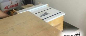
Purpose of straightening cutting machine
Straight steel wire is used in many areas - mechanical engineering, for the construction of buildings and structures, and in the creation of complex metal structures. In this case, special requirements are imposed on its geometric parameters.
Since in most cases the blanks are supplied in coils, before using them it is necessary to perform the process of leveling and forming sections of a certain length. Manual labor will not allow this task to be completed with the required level of strength. To do this, straightening cutting machines should be installed.
They are designed to perform the following functions:
- alignment of steel bars. This is done using a system of shafts that are located on the feed and broach line;
- block with guillotine. Designed for cutting workpieces of a certain length.
During operation of the equipment, the diameter of the wire should not change. To do this, you need to correctly set the parameters of the broaching unit.
The material used to make the workpieces must be taken into account. Depending on this, the optimal cutting force is determined.
Kinematic diagram of the straightening and cutting machine I6119
Kinematic diagram of the straightening and cutting machine I6119
The feed and cutting mechanisms of the machine are driven by a four-speed electric motor 1 (Fig. 6.2). A drive pulley 2 is installed on the electric motor shaft, from which rotation, using a V-belt transmission, is transmitted to pulley 3, rigidly seated on shaft I. The gear drive of the machine is equipped with two electromagnetic clutches that operate alternately. When clutch 22 is engaged, rotation from shaft I through gears 8 and 9 is transmitted to the lower shaft IV of the rear feed mechanism, on which gear 10 is attached, which meshes with the same gear of the upper shaft V. Thus, the feed rollers 14 of the rear feed mechanism are rotated. The feed rollers 14 of the front feed mechanism are driven through a chain drive. Rotation from the drive sprocket 11 is transmitted to the driven sprocket 13, mounted on shaft VI, and through the idler gear 15 on shaft VIII
The lower feed rollers are installed on shafts VI and VIII. Rotation by the upper feed roller mounted on shafts VII and IX is transmitted through GO gears.
In the chain drive, a sprocket 12 is provided for tensioning the chain. When the electromagnetic clutch 23 is turned on, the rotation of blade I is transmitted through gears 4.5 to shaft II, and through gears 6 and 7 to cam shaft III.
To drive the movement of the lever 31 of the cutting mechanism, an axial knuckle 24 is installed on shaft III. The lever is connected to the axial knuckle by a conical roller 30.
The drive of the correct frame is carried out from a two-speed electric motor 17. Rotation from the drive pulley 19 mounted on the electric motor shaft is transmitted through a V-belt drive to a pulley 20 mounted on the shaft of the correct frame. A braking relay 18 is installed on the motor shaft. The list of kinematic elements is given in Table 6.3.
Operating principle of the machine
The front end of the wire coil from the unwinder is directed into the feed rollers of the front feed mechanism. Using a lever-eccentric mechanism 16, the rollers are clamped through a spring 37 and the wire is passed into the cracks of the correct frame. After passing through the frame, the wire enters the feed rollers of the rear feed mechanism. Straightening of the wire occurs when the correct frame is rotated due to the fact that the crackers are shifted relative to each other towards the axis of the frame, the wire is subjected to repeated transverse plastic bending.
The straightened section of wire, through a cutting sleeve fixedly fixed in the body of the cutting mechanism, is fed into the closed chute of the receiving tray until it stops 39, adjusted to the specified length of the metal being cut. When the wire is pressed, the stop moves along with the flag 36, which enters the groove of the contactless limit switch 29. The latter gives the command to turn off the electromagnetic clutch 22 of the feed mechanism and turn on the electromagnetic clutch 23 of the cutting mechanism.
When clutch 23 is engaged, cam shaft III rotates. The axial fist 24 drives the cutting mechanism lever. There is a knife mounted on the lever. When the lever moves, a piece of wire is cut. Simultaneously with the cut, the cover 35 of the receiving tray opens due to the fact that the cover is connected to the levers on shaft X, which receives a rocking motion through the lever 34 and the roller 33 from the cam 32 mounted on the cutting lever. After cutting the rod, the stop 39 returns to its original position using the spring 38.
With further movement of the shaft (flag 28 is set on it), the contactless limit switch 29 is triggered, which gives the command to turn off the cutting clutch and turn on the feed clutch. The machine has two BVKs (item 29).
The cam shaft is stopped by a permanent disc brake 27.
After completing one revolution of the cam shaft, the cutting lever returns to its original upper position, the tray cover, under the action of spring 40 and lever 41 connected to shaft X, closes the chute, and the operating cycle of the machine is repeated.
In order to avoid twisting of the wire at the time of cutting (the feed is turned off), the straightening frame together with the body 21 performs a translational movement from the eccentric 25 located on the cam shaft through the connecting rod 26.
The lid can be opened manually using an eccentric 42 and a lever 43.
The above cycle is called working with a stop (the stop with the springs will be mixed). It is possible to work without a stop - the wire does not come into contact with a movable (movable) stop, the feed clutch and the cutting clutch are constantly turned on simultaneously, i.e. the cutting shaft (cam shaft) constantly rotates, and after each revolution of the shaft the cutting lever carries out the cut. Work without a stop is usually used for testing at idle speed and when producing short workpieces (100 mm-350 mm) with a significant variation in length. When working with the stop, you can install the screw wiring (pos. 23 Fig. 6.12.), provided in the design of the machine. This will eliminate the possibility of moving the wire with the stop during the short time during which the signal to turn on the cutting clutch comes to it from the BVK. It is effective to use this wiring screw (hard stop) when working with two clutches turned on simultaneously at low wire feed speed.
Review of straightening machine designs
The standard equipment includes a correct frame with a shaft system, a pulling mechanism and a cutting unit. In addition to the standard function, such an installation can restore the original geometric dimensions of a straight wire.
An important point is the choice of the optimal model. Wire straightening machines are classified according to several parameters. First, the location of the leveling shafts. They can be installed both horizontally and vertically.
The following types of equipment are currently being manufactured:
- standard. The formation of an even workpiece occurs due to the influence of the correct frame on it. In this case, the rod is bent transversely;
- medium-speed with inverter. To increase productivity, the package includes three independent electric motors. Two of them are designed for broaching, and the third provides a high feed speed;
- medium-speed with a flying guillotine. The main difference is that instead of an electric drive, a hydraulic system is used for the guillotine. In this case, the cutting block moves along with the wire;
- special purpose. Used for processing non-round products. An important component is the end shape of the rollers, which depends on the initial parameters of the workpiece.
In addition, the wire straightening machine can be operated either manually or automatically. In the latter case, it is necessary to have a control unit that will regulate the feed speed and power of the electric motors.
Models with a flying guillotine are used on construction sites. They provide processing of products with a diameter of up to 18 mm.
Location of controls for straightening and cutting machine I6119
Location of controls for straightening and cutting machine I6119
- Feed roller clamp handle
- Feed roller clamp handle
- Toggle switch for local lighting
- Output tray cover opening handle
- Handle of hand scissors
- Feed and cut motor stop button
- Feed button
- Cutting button
- Right frame engine stop button
- Wire feed reverse switch (forward, backward)
- Right frame motor start button
- Button for turning on the feed and cutting mechanism motor
- Signal lamp for correct frame drive motor operation
- Signal lamp for operation of the feed and cutting mechanism drive motor
- Signal lamp for “Adjustment” mode
- Signal lamp for "Automatic" mode
- Operating mode switch “Adjustment-automatic”
- Machine operation switch (with stop, without stop)
- Cycle button
- General (emergency) stop button
- Single-door electrical cabinet for one-sided service LxBxH = 600x400xl200
- Operating mode switch
- Motor speed switches for feeding and cutting mechanism drive (4 steps)
- Input (emergency) switch
- Workpiece counter
- Signal lamp: “Network”
- Motor speed switches for feeding and cutting mechanism drive (4 steps)
- Correct frame drive motor speed switch (2 steps)
Machine Specifications
When analyzing proposals for ready-made equipment, special attention should be paid to its technical parameters. They directly depend on the initial characteristics of the material being processed. To do this, you need to familiarize yourself with the technical documentation and read reviews from owners.
The determining criterion for selection is the type of straightening machine, which must correspond to the above-described classifiers. Then the maximum and minimum diameter of the workpiece being processed is taken into account. To ensure normal operation and convenience of personnel, the overall dimensions should make it possible to install the complex on a specific site of the production facility.
Main technical characteristics of the straightening machine for steel rods:
- maximum and minimum diameter of the workpiece;
- feed speed, m/sec;
- length of cut rods, m;
- cutting accuracy, mm;
- overall dimensions and weight.
The speed of changeover for processing rods of other diameters is also taken into account. Additionally, it is recommended to purchase a set of shafts for alignment.
The video describes in detail the design and operating principle of the straightening machine:
Information about the manufacturer of the straightening machine model I6119
The manufacturer of the straightening and cutting machine model I6119 is the Khmelnitsky Forging and Press Equipment Plant , founded in 1898.
Types of reinforcing steel straightening mechanisms and their features
Straightening machines can be reduced to two basic diagrams. The schemes cover modern and previously produced machines of domestic and foreign models.
Structural diagrams of straightening cutting machines
- coil of reinforcing steel
- roller straightening mechanism
- drum straightening mechanism
- collet pulling device
- roller pulling device
- measuring roller
- terminal switch
- lever knives
- rotating knives
- receiver
The operation of the straightening cutting machine occurs in the following sequence:
The reinforcing wire is unwound from a coil 1 and pulled through a straightening device 2 or 3 by means of a pulling mechanism 4 or 5, measured to a given length by a measuring roller 6 or a limit switch 7 and cut by parallel (lever) knives 8 or rotating knives 9. To ensure high cutting accuracy All modern domestic machines are equipped with limit switches 7 and lever knives 8, but in operation there is a large fleet of machines with rotating knives 9, equipped with both a measuring roller 6 and limit switches 7, which replaced the measuring rollers. On some of these machines, rotating knives are replaced by lever knives with pneumatic drive.
Roller straightening devices 2 do not provide high-quality straightening of round bars and are not used on modern domestic straightening machines. As independent roller mechanisms are used in combination with machines for welding meshes and flat frames, in bending lines, as well as on both foreign and domestic machines for cutting short rods. In such machines, insufficient quality straightening is compensated by periodic welding, which gives a plastic hinge, or by the short length of the prepared rod, or by plastic deformation of bending.
Refilling the roller truing mechanisms and adjusting the pressure elements takes a long time and is carried out using the trial and error method. On multi-point mesh welding machines, each longitudinal rod has its own multi-roller straightening mechanism. Some difference in the lengths of the rods in the skeins makes it difficult to simultaneously thread all the longitudinal rods.
High quality of straightening due to volumetric multiple plastic bending is achieved on drum straightening mechanisms 3, used on almost all straightening machines in combination with roller pulling devices 5 and lever knives 8, which, while ensuring high accuracy of the length of the cut rods, reduces the reliability of the machines. On such machines, the rod stops while cutting, and the drum continues to rotate. If the drum has 3000 rpm, and the stopping time is only 0.5 s, then during this time 25 alternating bends will occur under the pressure elements in the areas of the pressure elements in which, except for the extreme ones, the stresses will exceed the yield strength. This can be avoided by using flying shears, which accompany the moving rod during the cutting process and return to its original position. The accumulation of low-cycle fatigue phenomena on machines where, while the rod is stopped, the drum is given a reciprocating motion along its axis, is reduced. Such technical solutions significantly complicate the design of machine tools.
Drum straightening mechanisms are equipped with pressure elements in the form of dies and dies, which leads to the emergence of sliding friction forces when pulling the rod and rotating the drum around it. This, in turn, leads to increased wear, which increases when switching to straightening of periodic profile rods (in this case, partial cutting of the profile protrusions is observed), as well as with an increase in the strength of the processed rods due to an increase in the interaction forces between the rod and the pressure elements. The use of carbide dies significantly increased their durability, but the forces generated during the straightening process remained the same, and the durability of the remaining machine components was low.
Filling drum mechanisms with rods requires great physical effort, especially when filling with rods of increased strength and large diameters. The time for filling and adjusting the eccentricities of the pressure elements by an experienced machine operator is 3 – 5 minutes. for rods of small diameters, 5 – 8 min. and more for rods of large diameters. When straightening coils weighing 80–100 kg, this takes 10–50% of the working time. The use of the machine improves with increasing weight of skeins (skeins weighing up to 1000 kg are received). The duration of adjustment of the straightening mechanism is explained by the uncertainty of wear of the pressure elements. The adjustment is carried out by trial selection of the eccentricities of the pressure elements. As a rule, the first few rods of each skein have a curvature greater than the permissible one and cannot be used. Increasing the mass of skeins reduces the amount of scrap, but in the process of straightening large skeins, due to wear of dies or dies (not carbide), the quality of straightening may be impaired, and in this case it is necessary to stop the machine and additionally adjust the pressure elements of the drum straightening mechanism.
The main disadvantages can be eliminated by improving the straightening mechanism, in which it is necessary to maintain volumetric plastic bending, but eliminate sliding friction. This is achieved by replacing drum straightening mechanisms with vibration ones equipped with roller pressure elements. The moving sections of the straightening mechanism perform plane-parallel movement along a circular path and provide deformation of the rod of the same nature as in the drum mechanism. When pulling the rod through vibrating straightening mechanisms, sliding friction is replaced by rolling friction, which makes it possible to reduce the pulling force by almost an order of magnitude. The sliding friction that occurred in drum straightening mechanisms, which was caused by the rotation of the pressure elements around the rod, is completely eliminated. The use of vibration straightening mechanisms instead of drum ones on straightening machines reduces the energy consumption of the machines or ensures straightening of large diameter rods and periodic profile rods without increasing the power of the machine, while eliminating the partial cutting of profile protrusions that occurs in drum mechanisms.
Review of domestic straightening and cutting machines
Straightening cutting machines are used to pre-align the wire. We will look at their work and compare the machines SMZh-32, GD-162 and others.
Any enterprise that is engaged in the mass production of welding electrodes, or uses reinforcing bars for reinforced concrete on a mass scale, has at least one straightening and cutting machine for wire as part of its production equipment. Leveling and cutting machines are even more productive, the operation of which does not require the constant presence of an operator at the workplace.
Location of components of the I6119 straightening and cutting machine
Location of the main components of the I6119 straightening and cutting machine
Specification of the main components of the I6119 straightening and cutting machine
- Bed - I6119-11-001
- Feed and cutting drive - IV6118-21-001
- Correct frame drive - IV6118-22-001
- Chain drive - IV6118-23-001
- Gear drive and cam shaft - IV6118-24-001
- Correct frame - IV6118-31-001
- Cutting mechanism - IV6118-32-001
- Front feed mechanism - I6119-51-001
- Rear feed mechanism - I6119-52-001
- Receiving tray - IV6118-53-001 (attached equipment)
- Tool - I6119-61-001
- Hand scissors - I6418-62-001
- Machine guard - I6119-71-001
- Feed and cutting drive guard - IV6118-72-001
- Electrical equipment - I6119-91-001
- Control panel - I6122A-93-001-02 (attached equipment)
- Electrical cabinet - I6119-92-001
Device of straightening-cutting machines
The straightening and cutting machine consists of the following components:
- Electric motor;
- V-belt transmission;
- Reception shaft with flywheel;
- Electro-pneumatic friction clutch for drive engagement;
- Inertial unwinder;
- Feeding mechanism;
- Transfer mechanism;
- Ejection mechanism;
- Camshaft with bevel gear and control cams;
- The main crank shaft, on which a slider with a movable knife is mounted;
- Beds with a tool block where a fixed knife is installed;
- Adjustable swing type stop;
- Control unit.
The editing-cutting work cycle goes like this. The feed material from the unwinder periodically moves to the feed mechanism. The rollers installed there first straighten and then feed the material all the way into the cutting matrix. After this, the main drive of the machine is turned on: the movable knife cuts the workpiece to the required length and transfers it to the matrix. A calibration punch mounted in the slide pushes the workpiece into the die, where the upper and lower ends are calibrated. When the slider begins its reverse stroke, the rod is pushed out of the matrix and falls under its own weight into the container. The working cycle is automatically repeated until the unwinder runs out of wire.
Prices for straightening and cutting machines of domestic production range from 400 thousand rubles. up to 500 thousand rubles, depending on the size of the equipment.
Detailed video on how to make a proper cutting machine with your own hands:
I6119 Automatic straightening-cutting machine with a rotating straightening frame. Purpose, scope
Straightening and cutting machine - an automatic machine designed for straightening from coils of cold-drawn and hot-rolled metal of round section Ø 1.6..8.0 mm from steel supplied in coils with a tensile strength δ ≤ 800 MPa (80 kgf/mm2) and a yield strength of up to 500 MPa (50 kgf/mm), as well as cutting it into rods of measured length from 100 mm to 6000 mm, as well as into electrode blanks with a length from 200 to 450 mm.
It is used in hardware, calibration and procurement shops of metallurgical and machine-building industries, as well as in construction industry enterprises.
Operating principle and design features of the machine
From the unwinding device, the wire is directed into the feed rollers of the front feed mechanism, which, together with the rear feed mechanism, pulls the wire through the correct crackers of the rotating frame and feeds the straightened section through the cutting sleeve into the closed chute of the receiving tray until it stops, adjusted to the length of the rod. At the same time, signals are generated from contactless limit switches (BVK) to stop feeds, cut off the bar and open the tray, and the bar is lowered into the grippers. It is possible to work in the “without stop” mode.
The machine frame is cast from gray cast iron. All main working mechanisms are located on its upper plane.
The correct frame - a hollow shaft - is mounted in the bearings of the frame brackets. The frame rotation is driven by a two-speed electric motor through a V-belt drive. Straightening crackers are installed in the transverse through holes of the frame with an offset relative to its axis, which ensures alternating transverse bending of the wire during straightening. At the moment of cutting, the frame makes a reciprocating movement, which prevents the wire from twisting. The oscillatory motion is transmitted to the frame from an eccentric mounted on the cam shaft.
The drive shaft of the feeding and cutting mechanisms is rotated by a four-speed electric motor through a V-belt drive. Next, the gear drive and cam shaft communicate with the feeding and cutting mechanisms.
The front and rear feed mechanisms are structurally identical and carry two pairs of feed rollers. The rear feed mechanism is driven by a gear on the lower roller shaft, which receives rotation through an electromagnetic clutch from the drive shaft. The front mechanism is driven through a chain circuit from a sprocket mounted on the same shaft of the rear mechanism. The feed roller shafts are connected by gears. The clamping force of the rollers is adjusted by spring-loaded eccentrics. The band brake eliminates inertial rotation of the mechanism shafts.
The axis of the cutting mechanism lever and the cutting sleeve are attached to the housing of the rear feed mechanism. The swing of the lever carrying the cutting knife is carried out by the axial cam of the gear drive. The cam shaft is turned on by an electromagnetic clutch, powered by the BVK command. The cam shaft is stopped by a permanent disc brake. The BVK, which gives the command to turn off the cutting clutch and turn on the feed clutch, is triggered by a flag mounted on the cam shaft.
receiving tray . Each section consists of a gutter and a cover covering it from below, and is installed on composite racks. The opening of the chute occurs at the moment of cutting as a result of the action of the cutting lever and the cam mounted on it on the lever that turns the shaft connected to the cover. Returning the cover to its original position using a spring. The amount of overlap of the gutter stream with the lid is adjustable.
Receiving grips for rods are made in racks.
It is possible to manually open the tray in setup mode.
The length of the cut rod is measured using a rigid stop, which, under the influence of the supplied material, moves a slide with a flag for turning on the BVK, which controls the operating cycles of the electromagnetic clutches of the cutting and feeding mechanisms. The return of the spring with the stop to its original position is under the influence of the springs.
Counting of workpieces is carried out by a counter installed on the control panel, using pulses from the BVK.
Depending on the length of the workpieces to be cut, a bracket with a stop is attached to the construction site of the corresponding section.
The moving parts of the machine are covered by a fence.
Operating modes: adjustment, automatic.
Control is push-button.
Combined lubricant.
Climatic modification UHL4 according to GOST 15150-69.
Curvature is 1 mm per 1 m. The depth of the straightening mark is no more than 0.05 mm.
Cut bevel 0.15 d (according to GOST 10633-88)
The machine is manufactured with parameters according to TU 2-041-0222410-001-88.
Spun straight frame
The spun straightening frame rotates around the longitudinal axis and transmits bending loads in an overlapping spiral pattern, which ensures a high degree of straightness of the material being passed. The principle is that the circular and longitudinal effect of the die on the wire, transforming it into a spiral or wave, disappears when the wire enters the next die, blocking the hole in the previous one, and as a result, the output is a straightened, straight wire. Straightness depends on various factors, mainly feed, speed and the condition of the correct equipment.
How to choose machines for bending and cutting reinforcement for rent?
- Diameter of reinforcing steel – when choosing, it is worth starting from specific tasks. The optimal value is considered to be a maximum of 40 - 50 mm. It is with this type of fittings that craftsmen work most often.
- Power – it happens that the diameter of the reinforcing steel is the same for two machines, but one of them has more power. This means that it will cope with its task faster and with less load on the engine.
- Voltage - the vast majority of such machines are connected to a three-phase network. A rare exception is devices with a power of up to 2 kW. They can be powered from a standard 220 V household network.
- Weight and dimensions are parameters that are important for transporting equipment to the place of work. If you are looking for a machine for bending and cutting metal for rent and plan to pick it up, pay attention to this.
Today, concrete is perhaps the most popular building material, but now we are not talking about it, but about something that no concrete structure can do without - reinforcement. Reinforcement, which can now be purchased of any type, diameter and in any quantity, is used mainly to strengthen concrete structures or for the manufacture of mounting frames. This is a metal element most often in the form of a rod, although other types are also found - beams, profiles, pipes.
Types of fittings, scope of application, price of fittings:
1. Working (for foundation, walls and ceilings)
The type that takes on the main loads, for example, deformation of floor slabs under its own weight or external influences, is called working. Its diameter is selected depending on the size of the concrete structure and, as a rule, ranges from 10 to 40 mm, although when constructing something particularly massive, say, some dams or the like, which can withstand enormous loads, the diameter can be larger. Most often, reinforcement with a diameter of 12 mm is used for capital construction.
2. Distribution
It is best to tie the longitudinal rods of the working reinforcement together into something whole in order to distribute the load evenly, and the reinforcement that performs exactly this function is called distribution. As a rule, such fittings are 10 or 6 millimeters in diameter, that is, slightly thinner than the working one. The distribution rods are located across the workers and at the intersection points they are connected to each other by welding or simply twisted with wire, forming a rigid frame. Thus, not only is the load evenly distributed, but also the rods are fixed, which prevents them from moving during concreting. The frame itself, obtained from reinforcement, in turn, can also be divided into two types. Flat frame - one row of working reinforcement, fastened with transverse distribution rods. A kind of flat, two-dimensional network. This is the basis of most reinforced concrete structures, and, as a rule, with a small thickness of the slab, such a frame is more than enough. A spatial frame is several flat frames located parallel to each other and fastened together. This three-dimensional design is used when the concrete slab has a significant thickness, and one row of reinforcement is not enough.
3. Assembly
In cases where the purpose of the reinforcement is not to resist loads or distribute them, but to fix certain elements in the desired position, for example, the correct location of working reinforcement before pouring concrete, fixing clamps or fastening formwork, then this is called assembly formwork, it does not carry serious loads, and therefore, its diameter usually does not exceed 7-9 millimeters.
A1 (aka smooth).
The first type is smooth rods without any transverse ribs or notches. Such a product has a constant circular cross-section with a diameter of 6-40 mm and is mainly used where the loads will be directed towards compression, for example, as reinforcement for a foundation or walls, that is, as vertical rods. Of course, it can also be used in floors, but then when the rods are arranged horizontally, loops have to be made at their ends so that the smooth rods, which do not have the best adhesion to concrete, are held firmly inside the slab. There is no point in talking about the grades of steel from which it is made; a layman will not understand, but a specialist already knows this. It is worth saying only that it withstands welding well, so you can weld mounting frames from it without any problems.
Basic bending methods
If it is necessary to perform a small amount of work, then hand tools are used to bend the wire. For bending soft metal materials or when the wire diameter does not exceed 3 mm, pliers or round nose pliers are used. These tools allow you to securely clamp a part of the product in one tool, and use another to bend the wire to the desired angle.
In this way, you can bend the material using a carpenter's vice. In this case, the wire is fixed in a vertical position, and the change in direction is also carried out using pliers or any other clamping device or mechanism.
If it is necessary to make a rounded bend, then for this purpose any rod of suitable diameter is used, which is also clamped in a vice. A rounded bend will need to be made when making springs from elastic wire yourself.
To do this, it is enough to clamp a rod or pipe of a suitable diameter in a vice, fix the end of the wire on one side, and use pliers to wind the wire the required number of turns.
If the wire has to be bent too often, then the most correct solution would be to purchase special devices or machines.
Tools for bending this material are a design in which the wire is clamped and bent using human muscle power. Machine tools usually use electric drives, and for the manufacture of complex products such machines are equipped with electronic controls.
Rules for work
Wire bending is not a complicated process, but to work effectively with this material you must adhere to the following rules:
- For work, you must use gloves made of thick fabric.
- Use only working tools and automatic machines.
- If a vice is used to perform this operation, then before starting the process, you must make sure that the workpiece is securely fixed.
- Before bending, the workpiece should be leveled.
Following these recommendations will help prevent scraps and injuries in the event of a sudden release of material from the holding device. You should also take care of the wiring and proper grounding when using machines that run on electricity.
Equipment use
If the volume of work is large enough, then equipment equipped with an electric motor will allow you to perform a large number of operations. The use of machines will significantly increase labor productivity, but at the initial stage it will be necessary to make some efforts to study the process of operation of a wire bending machine.
The most economical machine for bending wire is considered to be coil equipment, in which the material is supplied from bulk coils.
The process of bending wire on such equipment is carried out in the following order:
- The wire from the coil is fed to a roller mechanism, which aligns the material.
- The straightened wire enters the bending mechanism.
- At the next stage, bending and separation of the wire products occurs.
- After cutting the finished product, the process is repeated.
To make wire bending work as comfortable as possible, CNC machines are used.
Design of the main components of the I6119 straightening and cutting machine
bed
The machine frame is box-shaped. It serves as the basis for all the main working mechanisms of the machine, which are located on its upper plane. An electric motor driving the correct frame is installed inside the frame.
Drive of the feeding and cutting mechanism of the straightening and cutting machine I6119
Drive of the feeding and cutting mechanism of the straightening and cutting machine I6119
The feed and cutting drive (Fig. 6.3.) is carried out from a four-speed electric motor 1 through a V-belt drive 2. The electric motor is located on the submotor plate 3. The belts are tensioned by tilting the plate using an adjusting screw 4. Speed switching is carried out by a switch mounted on the side electrical cabinet wall.
Correct frame drive
The drive of the correct frame (Fig. 6.4) is carried out from a two-speed electric motor 1 through a V-belt transmission 2. Electric motor. as mentioned above, it is installed inside the frame on a swinging sub-motor plate 3. Here, too, the belts are tensioned by tilting the plate using an adjusting screw 4. The electric motor speeds are switched by a switch located on the side wall of the electrical cabinet. When the frame drive is turned off (using the “stop” button, or when the frame guard cover is opened), the engine is automatically braked by the back switch to a rotation speed of 200..300 rpm, after which the braking relay stops the back switch braking, then the engine rotation stops.
Chain drive
The chain drive (Fig. 6.5) communicates between the rear and front feed mechanisms. Drive sprocket 1 is installed on the drive shaft of the rear feed mechanism, driven sprocket 2 is installed on the lower shaft of the front feed mechanism. The tension of the chain is carried out using a tension sprocket 3, freely sitting on an axis 4, fixed in a lever 5, which has the ability to rotate on an axis 6. At the other end of the lever 5, a pin 7 is screwed in, which fits into the groove of the bracket 8. The lever with the tension sprocket is locked nut 9.
Drive gear and cam shaft
The gear drive and cam shaft (Fig. 6.6) communicate the drive with the feed and cutting mechanisms. From flywheel 1, rotation is transmitted to shaft 2, on which gear 3 and freely seated gear 4 are rigidly fixed. The latter is connected through drive 5 to the driven disks of electromagnetic clutch 6, the hub of which is rigidly fixed to the shaft. When the electromagnetic clutch 6 is turned on, rotation from gear 4 is transmitted to gear 7 of the rear feed mechanism. At the moment of cutting, clutch 6 is turned off and gear 4 rotates freely, without transmitting torque, as a result of which the feed mechanism is turned off.
From gear 3, rotation through gear 8 is transmitted to shaft 9, on which gear 10 sits freely, connected through driver 11 to the driven disks of electromagnetic clutch 12. When clutch 12 is engaged, rotation from gear 10 is transmitted to gear 13, rigidly mounted on the cam shaft G4„ All shaft The gear drive is mounted on rolling bearings. The following are rigidly fixed to the cam shaft: an axial cam 15 of the cutting mechanism and an eccentric faceplate 16 that drives the oscillatory movement of the correct frame.
To make a cut, the cam shaft makes a full revolution. The cutting clutch 12 is turned off (and, accordingly, the feed clutch 6 is turned on) as a result of the action of the flag 18 on the contactless limit switch 17.
Braking of the inertial masses of the cutting drive when disconnected, the cutting coupling is carried out by a disk brake 19 of constant action. The disk brake springs are tightened with different forces in accordance with changes in the dressing and cutting modes.
The machine has an operating mode without a stop. In this mode, two electromagnetic clutches (feed and cut) are activated simultaneously. In this case, the brake must be released by releasing the brake springs 20.
Correct frame of straightening cutting machine I6119
Correct frame of straightening cutting machine I6119
Tool for straightening and cutting machine I6119
The regular frame (Fig. 6.7) is used for comprehensive straightening of round wire.” Frame I is a hollow shaft with five transverse through grooves, and in which there are 2 straight crackers, each of which has a through hole for the passage of the straightened wire.
When the crackers are displaced relative to the axis of rotation of the frame, the wire takes on a wave-like position, undergoing multiple transverse plastic bending. The crackers are installed in the frame using inserts 4 and secured with setscrews 3.
The correct frame at the moment of cutting performs an oscillatory back-and-forth motion to prevent twisting of the wire at the moment of cutting.
The body 5 of the correct frame is made in the form of a slider, which moves in the axial direction along the guides 6, which also serve to adjust and install the body. The oscillatory movement is communicated to the frame w of the eccentric, mounted on the cam shaft of the gear drive, through the connecting rod 7.
Frame 1 is mounted on rolling bearings. To straighten wire 0 1.6, the frame installed on the machine is replaced with a replaceable frame, included in the set of replacement parts of the machine and having 7 through grooves.
Cutting mechanism
The machine is equipped with a lever cutting mechanism (Fig. 6.8), which ensures the production of workpieces that are more accurate in length with good end quality. The cutting mechanism of the machine is mounted in a separate housing 1, which is attached to the frame using pins. The straightened wire is cut using a cutting sleeve 2 fixed in the body and an open knife fixed in the double-armed lever 3. The lever swings freely on an axis 4 installed in the body. The rocking motion of the lever is imparted by the axial cam of the gear drive, which acts on the cantilever conical roller 5. The axis 6 of the roller can be adjusted in the longitudinal direction using a screw 7 to compensate for wear of the roller during operation. The knife in the lever can be adjusted both in the vertical direction due to the screw 8, and in the horizontal direction due to changing the position of the clamping bars (wedges) 9.
A cam 10 is attached to the cutting lever, which is in contact with a roller installed in the lever, which belongs to the receiving tray. The rocking motion of the cutting lever is transmitted through the receiving tray lever to the shaft, which is connected to the receiving tray cover by levers. Therefore, at the moment of cutting, the chute of the tray opens.
Feeding mechanisms
The machine has two feed mechanisms; anterior (Fig. 6.10,6.11) and rear (Fig. 6.9.). These mechanisms are connected to each other by a chain transmission.
The drive of the rear feed mechanism is carried out through gear 1, sitting on shaft 2 and interlocked with sprocket 3. Through gears 6 and 7, the upper shaft 9 receives rotation. The balls of the mechanism are installed in rolling bearings. At the front ends of shafts 2 and 9 there are feed rollers 10. The support of the upper shaft on the side of the feed rollers is located in the slide (box) 11.
The rollers are clamped using an eccentric 12.
When turning the handle 13, the eccentric, through the screw 14, acts on the cup-nut 15 in which the spring 16 is inserted. Through the washer 17, the spring rests on the slide 11. In the clamped state, there should be a gap of up to 1.5 mm between the washer 17 and the head of the screw 14.
When expanding the feed rollers, the gap between the washer and the head of the screw 14 is first removed. As a result of this, the spring 16 is turned off. With further rotation of the eccentric, the spring 18 lifts the slider 11, and with it the upper shaft. The extreme positions of the eccentric are limited using limit pin 19.
The front feed mechanism is driven from the rear through a sprocket 6 sitting on shaft 1. The mechanism includes two pairs of feed rollers 10. The upper rollers are installed on shafts 2;4, the lower ones on shafts 1;3.
The transmission of rotation from shaft 1 to shaft 3 is carried out using an idler gear 5 located on the axis 7 on bearings 8. The transmission of rotation from shafts 1 and 3 to shafts 2 and 4 is carried out using gears 9.
The supports of shafts 2 and 4 on the side of the feed rollers are located in sliders (axleboxes) 11. Clamping of the feed rollers of the front feed mechanism is carried out in the same way as in the rear feed mechanism.
Oil baths are provided for the gears located inside the housings of the feed mechanisms. Oil levels are monitored by oil indicator rods 21 (Fig. 6.9).