The most interesting and useful devices for construction
When building any object, be it a house or something else that requires lifting heavy objects to a height, you need to go in two ways.
The first and easiest way is to hire people to lift heavy materials such as mortar, concrete or something similar.
Second, make a lifting mechanism capable of lifting heavy loads.
This device can replace at least three people and it is made of an aluminum ladder and an electric hoist.
Such a lift is capable of lifting three buckets of concrete and can be used alone. It’s not difficult to make a welded frame on bearings, and anyone with a little knowledge of electric welding can easily attach an electric hoist to the top of a ladder.
If you attach the electric hoist as shown in the photo to a well-reinforced beam, then you will get a very convenient device that can easily replace a crane.
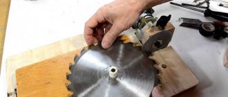
This simple device will speed up your work on grinding grooves when building from round timber. Using the same principle, you can make other devices for carpentry work.
With the help of such a simple device, you can not only break walls with virtually no noise, but also press metal parts during installation and hold together floor boards during installation.
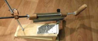
A very convenient device, especially in the manufacture of fencing and other work involving a large amount of work with bent wire and fittings.
I also have experience working with almost the same device when making fences, and I liked that the speed of work increases significantly.
Making such a device for cleaning walls from paint will not take much time; for this you need a welding machine, an old drill, and by welding a metal plate to the drill, you can increase the speed of cleaning the walls using a hammer drill.
Using an attachment that you can buy in a store today and a construction vacuum cleaner, you can remove paint from the wall with virtually no dust.
Homemade mini crane
Regardless of the height of the structure, the weight of concrete blocks always remains the same. To make work easier during construction, you can make your own crane. It is not difficult to assemble a small crane with your own hands with a lifting capacity of about 200 kg. The equipment is intended for domestic use and weighs 200-300 kg. This is a convenient model, easy to assemble and disassemble. Small dimensions allow you to transport equipment in a pickup truck. Prepared drawings will help simplify the assembly process; they include the following information:
- The basis of the structure consists of a cargo winch and supports. For the first, a gearbox with a worm base is used. With its help it is possible to create a manual drive. Then assembling the boom winch will become easier. Construction supports serve as a base for external screw parts.
- Winches need a base. It is made from an electric motor rotor. All parts must match each other in size, so they are carefully measured with a ruler. You won’t be able to make the base yourself, because this requires special equipment.
- The platform is equipped with wheels, this will simplify the movement of the crane along the surface.
- To ensure that the crane stands stable and does not lose balance, the boom is set to zero level.
- An arrow is made from a pipe with a diameter of up to 8 cm. Its acceptable height is 5 m. A profile of 2 corners is installed in the base.
- A turning mechanism is created from a car hub. He will be responsible for the rotation and lifting of the boom. The hub can be used from any cargo transport.
- Simple bricks are suitable as a counterweight.
- The crane is installed on a frame from an old machine or on a caterpillar track.
- Since the equipment operates at low speed, the turning mechanism and winch do not need a brake.
To make a garage crane, you will need: a hand winch, a cross pipe and racks on wheels. Pipe fasteners are welded at the top of the racks. The manual winch is mounted on a vertical stand. You can buy a ready-made winch or make it yourself. For self-production, a drum with cables is used, which is mounted on a structure made of pipes. A large sprocket with a chain is attached to the drum, and a small one is attached to the electric drive. If the winch is manual, the shaft with the drum is supplemented with a handle. To move the cable, rollers are required; they are mounted on the beam.
The result is a compact device that will not take up much space and will be easy to disassemble. The finished crane will be able to move loads of up to 800 kg.
How to make useful mechanisms and tools for construction with your own hands
It doesn’t matter whether you’re building your dream home or renovating an old country house, you can’t do without reliable tools and construction equipment. Almost any device today can be bought in a store, but purchases are not always pleasing with quality and even less often with prices. Our forum members know how to reduce the burden on the family budget and offer recipes for proven mechanisms and tools for construction, made with their own hands.
Truck...from the old four
Bring sand, crushed stone, boards, transport a concrete mixer and an old refrigerator... The need to deliver materials and tools during construction arises constantly. FORUMHOUSE member g8o8r8
found a way to save on freight transportation: he converted his old four into a truck!
Read also: Eyelet for lifting loads
Budget auto tuning cost the craftsman 3.5 thousand rubles - this was the cost of materials: an iron square, corners, galvanized steel for the loading body. Loading body g8o8r8
made it high to protect it from rainwater: to close the gaps between it and the car body, metal canopies were welded around the perimeter.
The rear side of the body is lifted with a 12-volt electric winch. This is convenient when unloading bulk materials and loading boards, stones, furniture, etc. into the body.
g8o8r8 (FORUMHOUSE Member):
At our metal collection point, they give five thousand rubles for any car. This inspired the idea of using my decommissioned four-wheeler for household needs: bringing earth, peat, stones, sand to the dacha. And if you install a subframe, weld a blade, install chains, you’ll see that you’ll be able to throw snow in the winter.
Construction materials lift
Another useful homemade product that will make life at a construction site much easier is a building materials lift. For example, like the one from FORUMHOUSE member Ali-bastr
Having started pouring monolithic walls, the forum member got tired of manually lifting heavy buckets of concrete and made a simple but ingenious design.
The basis of the lift was a metal staircase. To securely fix the ladder on the wall, in a 15×15 Ali-bastre
I drilled holes and put a washer on the back side of the pipe, securing it with a cotter pin. The trolley on which building materials are placed moves up and down on bearings No. 304 using an electric winch. It is located almost parallel, at a slight angle to the stairs, due to which the movement occurs smoothly.
Ali-bastr (FORUMHOUSE member):
It’s not for nothing that they say: laziness is the engine of progress. My lift lifts six buckets of concrete easily!
Planer for aerated concrete
Aerated concrete is one of the most popular modern materials for the construction of stone houses. The large format of the blocks and the installation technology, which can be easily mastered, allow even novice builders to erect buildings quickly.
But despite all its advantages, aerated concrete has a significant disadvantage - the blocks do not match in size and the need to adjust them to each other. You can use a shop tool for these purposes. But our forum members suggest making a plane for aerated concrete with your own hands. For this you will need: a board 5 cm thick, 3 wood files, universal glue, a door handle.
worodew (FORUMHOUSE Member):
Cut the files in half. We cut grooves in the board to half the thickness of the blade, lubricate the grooves with glue and insert the files. Screw the handle on and you're done.
Mobile foam cutting machine
And for those who insulate their house with polystyrene foam, another homemade product from the forum will come in handy - a machine for cutting polystyrene foam, which allows you to cut pieces of the required size simply and quickly, without bothering with a hacksaw and a ruler.
Our forum user Oleg Lvovich
To make a mobile machine, I used a 25x25 mm wooden strip 1.3 meters long, nichrome wire with a cross-section of 1 mm, a spring, two 20x4 mm steel strips, a 220/36V transformer and a 15-20 meter wire.
On FORUMHOUSE, a forum member shares a diagram of a homemade machine:
Unlike stationary cutting machines, this device can be freely moved around scaffolding and cut foam directly on site. At the same time, the sheet can be expanded not only in length, but also in thickness - for this, two profiles are additionally attached to the EPS with nails. According to a forum member, the cost of a mobile machine is 800-1000 rubles, and even with intensive use it will faithfully serve for several construction seasons in a row.
Other examples of machines for cutting foam plastic, including stationary ones, are in this topic.
Structure of the material and principles of its storage
Drywall consists of two components, which appear in its name. The gypsum base is covered with a layer of paper, which tightens it and prevents it from cracking. This structure makes the gypsum sheet (gypsum board) resistant to serious longitudinal loads. At the same time, its lateral stability remains quite weak.
Almost any pressure can lead to the formation of dents or even the appearance of through holes. Due to the large area of the sheet (2400x1200 mm), during the moving process its corners often suffer, breaking off or getting knocked down. According to building codes, the rules for storing drywall are based on the following principles:
the storage temperature of the material should not fall below 10 degrees (the optimal values are 16-18 degrees); humidity in the premises should be 75-80%; a room with good working ventilation, ensuring the circulation of air masses of at least 3 cubic meters. m/hour per 1 sq. m area; a ventilation gap of about 10-15 cm is left between the sheets and the floor surface (to ensure the necessary conditions, the material is laid on wooden slats); the best option for storing drywall is a horizontal position with 3-4 points of support (you should not stack more than 15-25 sheets in one stack, since the lower sheets may burst due to the increased load); the laid sheets are covered with a film designed to protect them from construction debris or other types of pollutants.
It is best to store drywall in a room where you can organize all the necessary conditions for its safety. Storing material outside is a temporary measure and is carried out exclusively in the warm season. It is better to place it on the roof or attic, where it will be completely protected from precipitation.
Comfortable grinder
Have you noticed that holding a small grinder by the top handle is convenient, but a large one is not? The big one always tries to escape from your hands when biting into metal. Having such a sad experience, some are generally afraid to use a large grinder. So that the grinder always remains in your hands, forum member chichic
designed a homemade handle for the instrument with a natural grip.
сhichic (FORUMHOUSE Member):
A powerful grinder can break out a cutting disc stuck in the metal, but it always remains in your hands. Proven by ten years of experience and cutting metal up to 14mm.
DIY cyclone vacuum cleaner
Dust and small debris during construction or major repairs are a real problem, which is difficult and ineffective to combat with a broom and rag. To make the cleaning process easier without spending money on expensive equipment, FORUMHOUSE member zalman3000
I quickly assembled a cyclone for a vacuum cleaner from scrap materials.
Zalman3000 (FORUMHOUSE Member):
I needed: a 20 liter plastic barrel, a 45 degree 40 mm angle, a 90 degree 32 mm angle, an oil filter from Moskvich (it fits tightly at the 32nd angle).
The simple design is attached to the vacuum cleaner, and waste is collected directly into a capacious plastic container.
You can discuss the article and read other materials on country life on the FORUMHOUSE portal.
A homemade crane for dismantling an engine, a photo of making a dismountable crane, and a video of testing a homemade product.
One day the idea arose to build a crane for dismantling a car engine, since there is not much space in the garage, which means we need to make a collapsible one!
Read also: How to use a screwdriver with a video indicator
To build the crane I needed the following materials:
- Profile pipe 80 x 80 mm (wall 3 mm) - 7 meters.
- Pipe 89 mm - two pieces 0.7 meters long.
- Pipe 76 mm - two pieces 0.9 meters long.
- Jack - 5 t (Soviet production).
- Metal plates 8 mm thick - 4 pcs.
- Hook from towing strap.
- Wheels 2 straight, 2 swivel + 2 swivel with brake.
- Studs M 14 - 1000 mm.
Next, I suggest looking at the drawings and the process of making the crane.
Crane drawings.
Tested my crane. I suspended a moped of 120 kg, then decided to climb onto the moped myself with another +120 kg - and again it seemed too little! But it is enough to dismantle the engine. I tried and lifted the Gazelle and took a video of the crane in action.
DIY crane
Do you really need a crane? So let's do it. Small-sized, with a boom that rotates and lifts, with a carrying capacity of two bags of cement, or 30 pieces of brick, or 3 large buckets of concrete.
I made one for myself, and now I can’t imagine how my wife and I could have built a two-story cottage with an area of 200 m2 if this crane had not existed.
Here are the drawings, and below is a detailed description of the process.
Just a tiny digression first: if anyone is looking for a simple lift for beams or logs, then take a look here.
Materials for the crane were mainly found in scrap metal. We only had to buy bearings, a winch, and order parts for the turning mechanism from a turner.
And I also had to pay a welder, since I myself cannot do welding work, due to some vision problems.
In general, this crane cost 5,000 rubles, which cannot be compared with the amount of work that I managed to complete with its help, because the “cheapest” helper in our region costs 800 rubles per day.
General view of my faucet
I’ll immediately make a reservation that during operation, my faucet revealed some shortcomings, which I will point out and advise on how to correct them. So your faucet will be a little different from mine.
Let's start with the rotating mechanism
It consists of six parts that need to be ordered by a turner, and two bearings.
As you can see, there are no dimensions in the drawing. The fact is that you don’t have to follow the exact size, like mine. After all, we make the faucet from available material, and I cannot know what size channel or I-beam, or what kind of pipe you will have at hand.
A little more or a little less doesn’t matter in my design. And you will understand this from further instructions. And having generally estimated what materials and parts you have, determine what dimensions to take for the manufacture of the rotating mechanism.
The mechanism has two bearings. At the top, between the housing and the base, there is a support bearing. Below, again between the housing and the base, there is a simple radial bearing.
Here you need to calculate the internal diameter of the body and the outer diameter of the base. Both of these parts must fit very tightly into the bearing.
Or rather, the housing should be mounted on the bearing, and the base should fit into it. Thus, both of these parts are connected. For more reliable fixation of the radial bearing, a nut is screwed onto the housing from below. The thickness of the threaded and retaining parts of the nut is at your discretion, but not less than 3 mm.
Then this unit is attached to the platform with a bolt (I have an M 26), which attracts the base to the platform. Thus, it turns out that the platform and base are a stationary part of the mechanism, and the body with the nut is rotating.
Now a little about what practice has shown. Towards the end of the season, the radial bearing weakened a little, and a barely noticeable play formed in the turning mechanism.
But with a boom length of 5 meters, this play became noticeably noticeable, so I recommend installing a hub bearing, 36 mm wide, instead of a radial bearing.
Here in Kazan, support and wheel bearings can be bought for 500 rubles both. And to tighten the bolt securing the base to the platform, you will need a spanner with an extension, and definitely two washers - a flat one and a lock washer.
Our next node will be the rack.
To make it you will need a piece of pipe (I have d140) and four pieces of channel. You need to estimate the height of the stand so that when finished it will be just right for you. Even two centimeters lower. Then it will be convenient to turn the winch when operating the crane.
Since God is unlikely to send you a piece of pipe with an evenly cut end, you will have to cut one end yourself. To do this, we take a car clamp, or make a clamp from a strip of tin, and tighten it on the pipe.
When tightened, the clamp will try to position itself on the pipe as evenly as possible, and if you help it a little (by eye), you will get a fairly even line around the circumference of the pipe, which you just have to draw, then remove the clamp, and cut the pipe along this line using a grinder .
Then, the rotating mechanism platform is welded to this flat end of the pipe. Now it’s clear why I didn’t give the dimensions in the drawing? You still have to order the rotating mechanism. And you can find a tuba. This means the diameter of the platform can be ordered according to the diameter of the pipe.
Now the legs. They need to be welded so that the stand does not collapse. How to do it? Firstly, they need to be cut to the same length.
Then hang the pipe with the welded platform, passing the rope through the hole in the center of the platform, and place your legs diagonally towards the pipe, so that in the end, the pipe remains hanging evenly, and your legs rest against it on all four sides.
As soon as the balance is found, you need to draw by eye the corners of the channels that abut the pipe, and trim them with a grinder as shown in the photo.
After trimming the corners, lean your legs against the pipe again, catch your balance, check with a rack and tape so that they form an even cross, and secure them with welding. After tacking, check the cross again, and you can weld.
All that remains is to make the support cross itself. It can be made from any rigid profile. At first there was an idea to put it on wheels made of bearings, but time was running out, and it didn’t come to the wheels, but actually it would have been nice. The unit turned out to be quite heavy, and it was difficult to move it.
The length of the arms of the cross is 1.7 meters, although as operation has shown, this cross does not play a particularly large role in the stability of the crane. The main stability is provided by balance, which we will talk about later.
The cross is not welded to the legs, but is attached with M 10 bolts and nuts. This was done for ease of possible transportation. The legs were reinforced in anticipation of installing wheels, but they never got around to it, although the idea of installing them is still there.
The stand with the rotating mechanism is ready, now let's move on to the crane platform, on which the counterweight, winches, and boom will be installed. I found a one and a half meter I-beam, 180 mm wide, for the platform. But I think you can use a channel and even a 150 x 200 beam under it.
At first I even wanted to use timber, but since I found an I-beam, I chose it. The platform is attached to the rotary mechanism body with four bolts and M 10 nuts.
If you use timber instead of an I-beam, then you will need to make additional platforms for it, above and below. You can “encircle” it with two pieces of channel and tighten everything with bolts.
But we’ll wait with the bolts for now, since the place where the platform is attached to the rotating mechanism will need to be selected based on balance. That is, the crane boom must be balanced by a block for counterweights and a winch. That is, the crane must stand confidently on the stand and not fall over.
Next will be the counterweight block.
I have it made from pieces of the same channel as the platform, but it can be made from anything, and in any way. The main thing is to have a container in which you can install loads, so that if necessary, you can increase the counterweight.
Now about the winch. My winch is installed with a capacity of 500 kg, with a brake. And once again, as practice has shown, such power was not enough to lift a load of about 100 kg.
That is, you can lift it, but you have to lean so hard on the handle that when lifting to a height of more than 5 meters, you get tired very quickly. For such a crane you need a winch of 1 - 1.5 tons.
There was also supposed to be a second winch for lifting the boom, but at that time, having visited a bunch of shops and markets, I could find only one winch with a brake, which you see in the photo. Therefore, instead of a second winch, a temporary tension cable was made, the length of which is still changed using clamps.
Unfortunately, there is nothing more permanent than a temporary structure. I still recommend that you install a winch instead, preferably a worm one. Its speed is low, and the brake, whether up or down, is dead. That's what an arrow needs.
All that remains is to make an arrow, which is what we will do. The boom consists of a mount with a shaft, a beam 150 x 50, and a tip with a pulley.
>
First, the mounting body. It is better to make it from a piece of channel wood.
Any round timber with a diameter of 20 to 30 mm will do for the shaft. For example, I cut off a piece of the rotor shaft of some old engine. Then we bend it in a vice, put two brackets around this shaft and fasten it to the channel, into which the beam will then be inserted.
We buy two simple bearings, so that they fit tightly onto the shaft, and cut out a seat in the mounting body.
Of course, you can dream up how to secure the bearings in the housing. Besides mine, there are probably a dozen more ways. And I found an ebonite plate, 10 mm thick, from which I made these fasteners.
The boom itself is a beam 150 x 50, 5 meters long. It is inserted into a channel 80 mm wide and 2.5 meters long. True, I had to trim it a little so that it would go inside the channel. I have a channel installed, 3.5 meters long, but this is only because at that time there was no good timber at hand with small knots. I simply played it safe, which, unfortunately, increased the weight of the arrow.
The timber is secured to the channel with ties made from a metal strip 3 mm thick.
At the end of the boom, you need to attach a pulley for the cable. Mine is made from a wheel from a trolley bag. For skilled hands, I think there are plenty of options for attaching the pulley. At first it was fastened between two pieces of plywood, but then I made a fastening from a channel.
Now you can assemble the arrow, if not for one “but”. During operation, the brackets with which the shaft is attached to the channel turned out to be rather weak. So I made them stronger.
And one more addition. My reinforcing part is secured with four bolts. You need to add two more on top to make the unit more rigid. Although mine works fine with four bolts. Otherwise I would have added it a long time ago.
Now you can assemble the entire crane platform, that is, install a winch on it, a block for counterweights under the winch, and at the other end - a boom lifting body with a boom. If there is, then a second winch, if not, then a guy rope, like I have.
All this is assembled in a lying position, and upon completion it is raised vertically, onto some kind of support. For example, I stacked several pallets on top of each other and placed the assembled platform on them so that the counterweight hung freely downwards.
Then we attach the rotating mechanism to the stand. The most important thing remains - install the platform on the stand so that the boom and counterweight balance each other.
Unfortunately, I don’t have any photographs of the structure that I built for this, well, I’ll try to explain it this way.
This design is a tripod with a block at the top. The height of the tripod is approximately three meters. It is made from 100 x 50 timber. As you probably already guessed, the assembled crane platform needs to be suspended and raised so that a stand can be placed under it.
The platform will be raised using its own winch. To do this, we pass the winch cable through the block and hook it to the boom lifting body, which is located at the opposite end of the platform.
Now, if you operate the winch upward, the entire platform will rise. But during the rise, the arrow, raised up, begins to collapse, so you need to either call a couple of assistants who will fix the arrow in a vertical position, or make another tripod (as I did) with a block 6 meters high, and tie rope to the end of the arrow, let it through the block, and pull it up as the platform rises.
Having suspended the platform in this way and placed a stand under it, you can lower and raise the platform and move the stand to find a position in which the counterweight will balance the boom.
In this position, drill 4 through holes and bolt the platform to the rack. OK it's all over Now. The tap is ready. You can start testing.
Well, a couple of examples of operation:
If the article does not answer your question, ask it in the comments. I will try to answer as quickly as possible.
I wish you success in your work, as well as the opportunity to lift and move everything you need and where you need it.
Section Construction >>>Subsection Tools and devices>>>
Hook lifting height:
From the ground with a short boom, the lowest point is 90 cm, the top 170 cm.
With a long boom - the bottom point is 80 cm, the top is 180 cm.
Long boom and unscrewed jack rod - bottom 140 cm and top 225 cm.
Throughout the long history of its existence, man has more than once been faced with the task of lifting and moving heavy objects in space. For example, the familiar Egyptian pyramids consist of massive stone blocks that no one can lift. Therefore, one of the greatest achievements of mankind is the invention of the lifting crane, which made it possible to significantly simplify the task of moving heavy loads and speed up the construction of houses and other objects.
Reliability and safety
In addition to cost, there are two more factors that cast doubt on the feasibility of making a lifting mechanism for a car with your own hands - reliability and safety. The weight of even a small car often exceeds one ton.
A car may fall off a lift for the following reasons:
- the weight of the machine turned out to be more than the drive or actuator can support;
- the locking device turned out to be of incorrect design;
- the locking device could not withstand the load;
- The lift supports are insufficient or incorrectly secured.
To make a lift with your own hands, you have to either take a ready-made diagram, hoping that its author has carefully calculated the strength of all the parts, or carry out these calculations yourself. Only a highly qualified engineer can do this kind of work; an ordinary car enthusiast cannot do it. In addition, it is necessary to calculate how much load the drive and brake mechanism can withstand. If any of these calculations are made incorrectly, the car lift turns into a deadly trap. No less important is the calculation of the basis of this mechanism. It is not enough to simply pour a thick layer of concrete, because it is necessary to provide fastenings located in strictly defined places.
Important Budget all-terrain vehicle BTX-2 with a lot of advantages for free movement on any terrain
Read also: Voltage stabilizer 220V photo
Search for parts
If you nevertheless decide to build a car lift with your own hands, and you are not afraid of the dangers of this homemade product, then start selecting parts by searching for the drive mechanism and stopper. These parts can be found in the following places:
- stores selling components for special equipment;
- enterprises that have old construction equipment on their balance sheet;
- enterprises that are updating their fleet of woodworking or metalworking machines;
- collection points for ferrous and non-ferrous metals.
For a scissor lift, you will need two hydraulic cylinders of suitable power and length, a compressor for them, and hydraulic hoses. The scissor circuit is the easiest to manufacture, but it is impossible to make a reliable brake in it. Therefore, if a hose bursts or one of the cylinders leaks, trouble cannot be avoided. Shafts and electric motors with gearboxes suitable for platform or fork lifts are easiest to find where old machines are replaced with new ones. This will cost much less than ordering worms from a turner. And the stopper of such mechanisms is not complicated - a helical bar with a lock, made of steel 1-2 cm thick.
Conclusion
If you still decide to take a risk and make a car lift with your own hands, then before choosing any scheme and starting assembly, find those who have already made such a device. See how it works, make sure it is safe. After all, you are not risking your car, but your life. If, when the car falls, one of your family members is under it with you, then you will put his life at risk.
To service a car in a service station, a bunch of special equipment is used, from cheap to very expensive, completely inaccessible to a private technician or simply a vehicle owner who is used to servicing the car with his own hands. There are very highly specialized devices that can be useful to a private owner once or twice a year. And there are those without whom any repair or prevention is simply impossible. Car lifts are just that case.
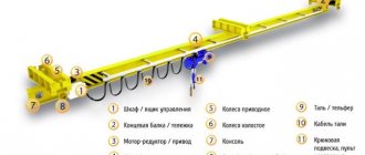
Machine structure
The operating principle of a crane is based on the physics of simple mechanisms. The simplest version of the crane is a stick placed on a fulcrum in such a way that the free ends have different lengths. Now if you hang a load on a short lever, it will take less effort to lift it. The most common design is one that uses, in addition to levers, a system of blocks.
A do-it-yourself crane is an indisputable assistant in small-scale construction. When constructing a private house, the use of bulky industrial cranes is not required. The height of the houses rarely exceeds 2 floors, and the weight of the lifted load is 200 kilograms.
Crane diagram
Although there are many variations of lifting mechanisms, a classic crane consists of the following parts:
- An arrow with a block attached to its end. Depending on its length, the height to which the load can be lifted is determined.
- Platform. The boom and counterweight are attached to it. It is the main part of the crane and is subject to significant loads. Therefore, when manufacturing a platform, it is important to pay special attention to its strength.
- Counterweight. Serves for crane stability. Defines the maximum load weight that the crane can lift. Stackable counterweight options are available to provide maximum stability.
- A guy wire connecting the boom and the counterweight. Allows you to adjust the tilt of the boom and move the load in both vertical and horizontal planes.
- Winch with cable. It is the lifting mechanism itself. The power of the winch determines how much weight the crane can lift.
- Stand with a rotating mechanism. It is necessary to turn the crane to the sides.
- The support cross, which is the base of the crane. Sets the stability of the entire structure. When manufacturing it, you should also pay attention to its strength.
How to do something yourself, with your own hands - home craftsman website
AN EXCELLENT TOOL FOR CRAFTERS AND HANDCRAFTS AND EVERYTHING FOR THE GARDEN, HOME AND Cottage LITERALLY FOR FREE - SEE FOR YOURSELF. THERE ARE REVIEWS.
The higher the walls of a house under construction grow, the more difficult it is to deliver building materials to the site. Renting a crane is expensive, so what can you do? Problems are solved by purchasing simple lifting mechanisms .
The arsenal of warehouses and large-scale racks includes everything: conveyors, escalators, gravity installations, loaders, cranes.
In private construction, simpler devices are usually used: blocks, hoists, winches and jacks. Some means are capable of moving the load only vertically, while others, if necessary, will pull it upward, horizontally, and even diagonally.
TOOLS FOR HOME AND GARDEN, HANDCRAFTS, ETC. PRICES VERY LOW
terms of Use
To operate lifting mechanisms safely, certain rules must be followed.
Homemade Pioneer crane
These rules apply to any lifting device:
- The load capacity must not be exceeded. A load that is too heavy may damage the device.
- The base must be stable. Homemade lifting devices should be located on a previously prepared hard horizontal surface.
- In bad weather conditions, you should also refrain from working with the crane. Strong winds will throw the crane off balance, and poor visibility may make it difficult to see people under the boom.
- Before operating a crane or lifting device, it is necessary to conduct an external inspection to identify any malfunctions. If malfunctions are detected, operation of the crane is prohibited.
- It should be remembered that when working with the lift, you should not make sudden movements. The load must be lifted smoothly. And most importantly, do not stand under any lifted load.
What characteristics should a garage lift have?
In garage conditions, two types of lifting mechanisms are used. The first type includes a lift that can lift the entire car, and the second type includes a goose-type lift that allows you to move loads around the garage.
Lifts of the first type are stationary devices and the main requirement for them is stability. The car weighs more than a ton and should not have the slightest chance of falling. In order to prevent any accidents, the garage lift must have a reliable stopper.
Homemade goose tap
The goose type lifts are most often used in auto repair shops. It is quite simple to make it from a profile pipe or channel. First, the base is welded on which the rotating mechanism needs to be installed. It is best to make an arrow with an adjustable reach. This will make it possible to move weights in any direction.
Read also: How to make your own vise for a drilling machine
Reliability and safety
In addition to cost, there are two more factors that cast doubt on the feasibility of making a lifting mechanism for a car with your own hands - reliability and safety. The weight of even a small car often exceeds one ton.
A car may fall off a lift for the following reasons:
- the weight of the machine turned out to be more than the drive or actuator can support;
- the locking device turned out to be of incorrect design;
- the locking device could not withstand the load;
- The lift supports are insufficient or incorrectly secured.
To make a lift with your own hands, you have to either take a ready-made diagram, hoping that its author has carefully calculated the strength of all the parts, or carry out these calculations yourself. Only a highly qualified engineer can do this kind of work; an ordinary car enthusiast cannot do it. In addition, it is necessary to calculate how much load the drive and brake mechanism can withstand. If any of these calculations are made incorrectly, the car lift turns into a deadly trap. No less important is the calculation of the basis of this mechanism. It is not enough to simply pour a thick layer of concrete, because it is necessary to provide fastenings located in strictly defined places.
Search for parts
If you nevertheless decide to build a car lift with your own hands, and you are not afraid of the dangers of this homemade product, then start selecting parts by searching for the drive mechanism and stopper. These parts can be found in the following places:
- stores selling components for special equipment;
- enterprises that have old construction equipment on their balance sheet;
- enterprises that are updating their fleet of woodworking or metalworking machines;
- collection points for ferrous and non-ferrous metals.
For a scissor lift, you will need two hydraulic cylinders of suitable power and length, a compressor for them, and hydraulic hoses. The scissor circuit is the easiest to manufacture, but it is impossible to make a reliable brake in it. Therefore, if a hose bursts or one of the cylinders leaks, trouble cannot be avoided. Shafts and electric motors with gearboxes suitable for platform or fork lifts are easiest to find where old machines are replaced with new ones. This will cost much less than ordering worms from a turner. And the stopper of such mechanisms is not complicated - a helical bar with a lock, made of steel 1-2 cm thick.
Conclusion
If you still decide to take a risk and make a car lift with your own hands, then before choosing any scheme and starting assembly, find those who have already made such a device. See how it works, make sure it is safe. After all, you are not risking your car, but your life. If, when the car falls, one of your family members is under it with you, then you will put his life at risk.
Cars tend to break down and require periodic maintenance, like any equipment. Access to the lower part in garage conditions is often impossible due to the lack of a lifting device. Having all the necessary tools, a lift equipped and ready for work, it is possible to replace the consumables of the chassis, transmission, and engine. Despite the fact that the device is in demand when repairing cars with your own hands, purchasing it for use for your own needs is very expensive. Maintenance can be performed no more than twice a year, so it is better to make units and components yourself.
How a simple block design works
The pulley system or pulley system has been known to mankind since ancient times. The classic system design consists of pulleys and cable. One pulley is called a block. Depending on the method of fastening, the pulley can be movable or fixed:
- Fixed block. It is attached to the support and plays the role of changing the direction of movement of the rope. Does not provide any gain in strength.
- Movable block. It is located on the side of the load and gives a gain in strength.
The principle of operation of a pulley block is similar to the principle of operation of a lever in the physics of simple mechanisms. The role of the lever in this case is played by the cable itself. In the case of a simple block of two pulleys, the movable pulley divides the rope into 2 parts and in order to lift the load the same distance, a rope twice as long will be required. The work of lifting the load is performed in the same volume. And the effort, due to the fact that the length of the rope has become twice as long, becomes half as much.
If there are more than 2 pulleys in the system, the gain in strength is approximately equal to the number of blocks. In the case of 3 blocks, the effort will be 3 times less, and 4 blocks will require only a quarter of the original effort.
Types of lifting devices
What the pulley for lifting loads and the construction crane have in common is the use of the idea of increasing force - the rule of leverage. In order to balance the load on the short side of the lever, you need to apply less force to its long side to the extent that the short arm is less than the long one. The ratio of forces at the ends of the lever is called the gear ratio.
You can balance and even lift a weight with an effort less than its weight, but the path made by the end of a long lever will be longer than that of a short one, just as less force was applied to lift it. There is no gain in work (F1*L1=F2*L2), but this is not required.
The use of Archimedes' principle is implemented in different lifting mechanisms, and how depends on the purpose of the lift. Designs differ in gear ratio, principle of force transfer, mobility, strength, and energy used. The most popular types for self-production:
- chain hoists;
- drum structures;
- lever mechanism.
Complex block system how to calculate power gain
If the system is designed in such a way that one simple pulley pulls another simple pulley, then this is already a complex system of blocks. To theoretically calculate the gain in strength, it is necessary to conditionally divide a complex chain hoist into simple ones and multiply the values of the gain from simple chain hoists.
For example, if the system consists of 4 blocks, and the first conditional simple pulley has a gain of 3. It pulls the second simple two-block pulley, also with a gain of 3. The total force that will need to be applied will be 9 times less. It is the 4-block complex chain hoist that is most often used by rescuers.
How to choose?
When choosing the right equipment, it always makes sense to familiarize yourself with the capabilities of the equipment.
The following criteria come first:
- the weight with which the mechanism operates can range from 30 to 50 kg;
- Considering the size of the ceilings, you should ask at what height the plasterboard sheets are delivered.
You need to know that such devices only work for lifting and cannot move loads.
The strength and solidity of the structure itself are important:
- parts of the internal mechanism and components must be made of strong and durable materials, so it is always better to choose models made of steel without polymer additions;
- a reliable base configuration is a guarantee of the stability of the lift; in this regard, the most worthy stand is considered to be in the form of the letter “H”.
Inexpensive models that lift drywall above 4 meters may be quite suitable for ordinary housing. If you need to fix the coating in hard-to-reach areas, different directions of fastenings are provided, and the best option would be a lift-spacer. It has a more complex design and thanks to this can be configured for diverse tasks. True, such functional models are much more expensive than standard ones.
In addition, you need to take into account auxiliary options that are not always needed when installing gypsum boards. But if they are available, the price of the device increases significantly.
Since there are manual and electric models, choosing electric equipment makes sense for large volumes of work. It helps increase assembly speed, but is more expensive. According to professionals, for irregular construction work it is better to choose manual structures, especially since they do not fail so often.
Methods for attaching a rope to a lifting mechanism
When creating complex pulley blocks, there are often situations when a cable of the required length for attaching the moving block is not at hand.
Crane for gas blocks
Methods for attaching a cable using general-purpose rigging:
- Using a cord. Using a self-tightening knot, the cord is tied to the main cable. As the load is lifted, the grappling knot moves along the main rope, thereby allowing the height of the load to be increased.
- Using clamps. In the case of using a steel cable, it is not possible to use a cord, so it is necessary to use special clamps.
We create a simple lifting mechanism with our own hands
Construction of a crane is not a quick task and is justified if it is required frequently or the volume of work is large enough. In cases where the load needs to be lifted urgently or this is a one-time operation, you can use improvised means.
To create a simple lifting device you will need a cord and two blocks. One block and the end of the rope are fixed motionless on the support. This will be the highest point to which the load can be lifted. We attach the second block to the load using slings or a hook. We first pull the rope along the block attached to the load, then pass it through the upper block. The gain in power will be 2 times. Using your own weight, you can easily lift a load weighing 100 kilograms to the required height.
DIY mini crane
If you add the ability to move the upper block along a guide, for example along a rail, you can get a do-it-yourself jib crane. It is useful in garage conditions for moving heavy machine parts.
It should be remembered that when working with the lift, you should not make sudden movements. The load must be lifted smoothly. And most importantly, do not stand under any lifted load. The same rule applies to a crane - standing under the arrow is prohibited.
Choosing a hoist
Manual chain hoist
, a small-sized lifting device, allows you to lift loads weighing up to 5 tons using only muscle strength. When choosing, first of all, you should focus on the load capacity. By the way, there are hoists with a built-in power unit - a pulley block - and without it.
Of course, when choosing a hoist, you need to take into account the tasks at hand. In mechanical models, chain lengths range from 1.5 to 12 m, so the lifting height matters. Also, of course, the weight of the hoist itself is important, which determines not only the possibility of its installation on a beam, but also the ease of transportation. Lightweight lever hand hoists weigh up to 20 kg. And purchasing a carriage for a hoist gives you some flexibility. The carriage is suspended on an I-beam and moves the hoist along it along with the load in a horizontal plane.
Materials and tools
The most important thing when making a crane is to use high-quality tools and materials. This will guarantee that the structure will be strong and safe.
The cable should have minimal stretch; this will give a greater gain in strength when using a pulley system. The fittings used for tying must be taken only from metal. Plastic fittings cannot withstand heavy loads and break at the wrong time. To fasten individual parts of a homemade crane, you should choose high-strength hardware products.
If a winch is intended to be used, its lifting capacity should not be less than 500 kilograms. The best choice would be winches that can lift a load weighing 1 ton or more.
In conclusion, I would like to once again remind you of the need to observe safety precautions when working with lifting mechanisms. Also, regardless of whether the crane is purchased or made by yourself, you should inspect it before starting work.
If you find an error, please select a piece of text and press Ctrl+Enter.
DIY garage lift
For your garage, you can make a pit lift yourself, which will be convenient to use.
This type of lift has a safe design, which is important for DIY projects, and is also easy to operate.
The height of our homemade structure will depend on the hydraulic jack used, which will lift the top, and the length will depend on the width of the pit in the garage. The lift carriage will be 35 cm high and 80 cm wide for a pit of the appropriate dimensions.
It will be equipped with rollers that are located along the width of the pit and will move this entire structure along the length of the pit. When manufacturing and installing the lift, it should be taken into account that the edges of the garage pit should be trimmed with corners along which the rollers will run.
Therefore, the selected rollers must withstand heavy weight and move freely along the corners installed along the length of the pit.
Materials for work
In order to make a structure for lifting a machine, you should stock up on the following materials:
- channel 100 mm - 1.5 m;
- corner 63 mm - 2.5 m;
- corner 50 mm - 2.5 m;
- square steel pipe 40 mm - 0.6 m;
- square steel pipe 50 mm - 0.5 m;
Step-by-step instruction
To make a lift, follow these steps:
Cut the base of the structure from a 100 mm channel (80 cm for the bottom and 2 pieces of 35 cm for the sides). First grab them and then cook them
At the same time, it is important to monitor the stability of the structure and fit the parts tightly to one another. From a 63 mm corner, cut 2 side parts for the lift carriage to a width of 35 cm. Also grab and weld on the sides at the top of the resulting base structure from the channel
Where the guides extend in the corner, cut a square with a side slightly less than 50 mm. Weld guides from a 50 mm square to the sides of the carriage from a 100 mm channel to a cut out square, into which the retractable upper part will be inserted with its two guides from a 40 mm square. Cut 2 pieces from a 50 mm profile (80 cm in length) and weld them in the upper part of the carriage to the side corners, leaving space between them for the upper part, which can be pulled out with a jack. Install the rollers to the side upper corners 63 mm. Install 2 rollers on each side, the distance between them is approximately 28 cm. The rollers should clearly fit into the corners on the sides of the pit. Make the upper retractable part of the lift. To do this, you need to cut and weld together 2 identical corners of 63 mm, each 90 cm long, making them into a hollow square pipe. Then weld 2 guides made of a 40 mm square, 30 cm long, to the corners welded together, without reaching their ends. The guides, together with the gap with them, should take up a little less than 80 cm. Weld a reinforcement made of a 40 mm square to the welded corners between the guides. The top extension should fit snugly in and out of the base guides.
Video: making a car lift with your own hands
Installation
If you have taken into account all the important aspects of the relationship between the width of the pit, the height of the jack and the dimensions of the structure itself, then the lower part of the channel should freely fall into the pit, and the rollers on the upper part should be located along the width of the pit and move along the corners installed along its length.
A hydraulic jack is installed on the lower part of the channel in the middle, which, if necessary, is activated and lifts the upper sliding part, which lifts the car. You can also store special paw attachments used as extension cords there.
Correct operation
When using a lift, you usually do the following:
- The guides should be lubricated, for example, with grease for better removal from the lift. The condition of the lubricant should always be monitored and renewed as necessary.
- Extend the paw to the required distance and insert the turned paw with the required extensions into it.
- The vehicle being lifted must be secured with the handbrake - make sure of this.
- The jack needs to be tightened and raised to the desired height.
- It is permissible to go under the car only after the lift has stopped operating.
- It is forbidden to stick your head or limbs between the sides of the lift.
- Do not place your hands or fingers near the rollers.