06/08/2020 Author: VT-METALL
Issues discussed in the material:
- Gas welding principle
- Scope of gas welding
- Pros and cons of gas welding in general
- Advantages and disadvantages of the left-hand method of gas welding
- Advantages and disadvantages of the right gas welding method
- Criteria for choosing left and right welding methods
- Other popular gas welding methods
- Safety precautions for gas welding
There are various methods of gas welding. Some of them are more in demand, others less. Each method has a certain set of advantages and disadvantages - the choice depends on the specific situation.
In one case, the most effective method of gas welding will be the right one, in the other - the left one. Sometimes welding using pools is necessary, sometimes using a through bead. Which method is best to use and when? This is discussed in our article.
Gas welding principle
The peculiarity of the gas welding method is that during operation a stream of hot gas is supplied to the welding area. It heats the joining surfaces of the workpieces to a critical temperature and liquefies the filler material. The latter is supplied to the heating site from the opposite side or is fixed directly to the nozzle.
All known gas welding methods involve protecting the material from the formation of an oxide film due to the fact that air is displaced from the site of exposure by a special gas. After the seam cools smoothly, the elements are firmly fastened together. To perform this type of work, several types of gas are used:
- hydrogen and oxygen;
- oxygen and acetylene;
- methane and oxygen;
- propane and oxygen;
Methods for gas welding of metals allow the use of any flammable gas with an admixture of oxygen, but acetylene is best suited for these purposes. Its operating temperature reaches +3400 °C, while propane is only +2800 °C.
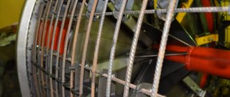
Gas welding with high power flame
With this method of gas welding, the torch is used with a power twice as high as with the conventional welding method, and a flame is set with an excess of acetylene by 7-10%. The edges of the metal are heated only until melting begins. Gas welding of steel is carried out as follows. The edges are heated by a carburizing flame, as a result of which their top layer is enriched with carbon and the melting point of the metal decreases. At a temperature of 1200°C, the edges begin to melt (sweat). At this time, a filler wire heated to melting is introduced into the weld. The molten metal of the wire dissolves the carburized top layer of the base metal and is firmly bonded to it. Deep melting of the edges cannot be done, as this will result in a high-carbon, brittle layer.
The wire diameter is larger than in conventional welding. Edge bevel 60-70°C. Gas welding is performed in the right way. This method provides greater welding speed, but requires a highly qualified welder.
Scope of gas welding
The use of gas welding allows you to solve such production problems as:
- soldering (including repair work);
- surfacing;
- cutting rolled metal and metal pipes into individual parts;
- welding of elements into one structure.
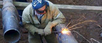
Gas welding machines are often used in industrial production and garage workshops, construction and auto repair shops, as well as in public utilities. With the help of such a unit, various elements of complex structures, thin-walled pipes are connected, and joints of products made of non-ferrous metals are made.
Soldering and cutting, performed using gas welding, allow you to achieve the desired result with the proper quality.
Soldering is carried out due to three key factors: strong heating of the edges of the elements being connected occurs, the solder melts, and a special antioxidant substance - flux - is added to these two components. Due to the mutual penetration of solder molecules and the material of the structural parts (diffusion), a strong, neat seam is formed at the joint. If necessary, it can be subjected to further processing.
Surfacing is the coating of a base material with a layer of metal with other characteristics. To do this, the soldering surface is preheated to the “fogging” temperature. Using this method of gas welding, worn surfaces are often repaired, parts are lengthened or expanded, and the wear resistance and strength of elements are improved. Thanks to this, you can reduce the cost of repairs, reduce the consumption of rare or expensive materials, and extend the service life of the product.
Pros and cons of gas welding in general
Any method of connecting metal elements into a single structure has its advantages and disadvantages. The gas welding method, for example, is distinguished by the fact that under a stream of gas the working surface heats up relatively slowly. However, it is impossible to clearly determine whether this is good or bad.
The advantages of this heating intensity of the working surface include:
- Smooth thermal effect. This property is especially important when working with non-ferrous metals.
- No need for a powerful power source.
- Possibility to adjust the strength of the hot gas jet.
- Ease of switching operating modes due to additional controllers.
Disadvantages of slow heating of the working surface when using the gas welding method:
- Most of the heat during operation is dissipated in vain, so this method of connecting parts has low efficiency.
- Due to the increased heat impact zone, it is impossible to perform work that requires high precision.
- The economic costs of gas when performing work of this type exceed the costs of electricity.
- The components of gas welding equipment (hoses, cylinders, etc.) are not easy to transport.
- To obtain high quality seams, extensive practical experience is required.
Much of this type of equipment for metal cutting or welding is manually controlled, so in such cases it is impossible to automate the production process. Today there are two main methods of gas welding: left and right. Let's take a closer look at each of them.
Advantages and disadvantages of the left-hand method of gas welding
The operating principle of the left-handed method is that the nozzle moves from right to left. In this case, the flame tends forward to the still unheated area of the product, and the filler material is fixed in front of the fire flow. Uniform diffusion and heating of the edges of parts is ensured by zigzag movements of the apparatus.
This method allows you to achieve high quality seams with the same height and width, as well as impressive efficiency at low financial costs. However, you will get all this only if the metal thickness using the left gas welding method does not exceed 3 mm.
We recommend articles on metalworking
- Steel grades: classification and interpretation
- Aluminum grades and areas of their application
- Defects in metal products: causes and search methods
This feature is due to the fact that the flame heats the metal lying in front. The left method is considered less complex and requires less skill.
As a rule, it is used for working with 2-3 mm steel workpieces, as well as for metals with a low melting point. When processing parts thicker than 5 mm, the right method will be faster.
The diameter of the filler wire for left-hand welding is determined by the formula:
The advantages of the left method are as follows:
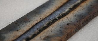
- the seam is aesthetically pleasing – smooth with a slight scaliness;
- there is little thermal impact;
- quickly and efficiently copes with workpieces thinner than 3 mm.
Disadvantages of the left method:
- a lot of heat is lost;
- the weld pool is ahead of the movement of the apparatus;
- difficult to regulate penetration;
- the effect of the protective atmosphere is limited in space.
Gas welding technique
Gas welding methods
There are two methods of gas welding (Fig. 92):
left-hand welding, in which the torch is moved from right to left and held behind the filler wire. In this case, the welding flame is oriented towards the seam that has not yet been welded. This method does not sufficiently protect the metal from oxidation, is accompanied by partial heat loss and gives low welding productivity; right-hand welding, in which the torch is moved from left to right and held in front of the filler wire. In this case, the flame is oriented towards the completed weld and the end of the filler wire. This method makes it possible to direct a larger amount of heat to melt the metal of the weld pool, and the oscillatory transverse movements of the nozzle and wire are carried out less frequently than with the left method. In addition, the end of the filler wire is constantly immersed in the weld pool, so it can be used to stir it, which promotes the transition of oxides into slag. The right method is usually used if the thickness of the metal being welded exceeds 5 mm, especially since in this case the welding flame is limited on the sides by the edges of the product, and at the rear by a bead of deposited metal. Thanks to this, heat loss is reduced and it is used more efficiently. The left method has its advantages, since, firstly, the weld is always in the welder’s field of vision and he can adjust its height and width, which is of particular importance when welding thin sheet metal; secondly, when welding, the flame can spread over the surface of the metal, reducing the risk of burnout. When choosing one or another welding method, one must also be guided by the spatial position of the weld: when making the bottom weld, the thickness of the metal should be taken into account. It can be applied both right and left. This weld is the easiest because the welder can observe the process. In addition, the liquid filler material flows into the crater and does not pour out of the weld pool; For a horizontal seam, the right method is preferable. To prevent liquid metal from leaking out, the walls of the weld pool are made with some distortion; for a vertical seam on the rise - both left and right, and for a vertical seam on the descent - only the right method; it is easier to apply a ceiling seam in the right way, since the flame flow is directed towards the seam and prevents liquid metal from flowing out of the weld pool. A method that guarantees high quality welds is pool welding (Fig. 93).
Rice. 92. Methods of gas welding (the arrow indicates the direction of welding): a – left; b – right; 1 – filler wire; 2 – welding torch
Rice. 93. Welding with baths: 1 –
welding direction; 2 – trajectory of movement of the filler wire; 3 – trajectory of the mouthpiece
This method is used for welding thin sheet metal and pipes made of low-carbon and low-alloy steels with lightweight seams. It can also be used when welding butt and corner joints with a metal thickness of up to 3 mm. The pool welding process proceeds as follows: Having melted metal with a diameter of 4–5 mm, the welder places the end of the filler wire into it. When its end is melted, he introduces it into the reducing zone of the flame. At the same time, the welder, slightly moving the mouthpiece, makes circular movements with it in order to form another bath, which should slightly (by about a third of the diameter) overlap the previous one. In this case, the wire must continue to be kept in the reducing zone to prevent its oxidation. The flame core must not be immersed in the weld pool, otherwise carburization of the weld metal will occur. When gas welding, seams can be single or multi-layer. If the metal thickness is 8-10 mm, the seams are welded in two layers, with a thickness of more than 10 mm - three layers or more, and each previous seam is first cleaned of slag and scale. Multi-pass welds are not used in gas welding, since it is very difficult to apply narrow beads. During gas welding, internal stresses and deformations arise, since the heating area is more extensive than, for example, during arc welding. To reduce deformations, appropriate measures must be taken. To do this, it is recommended to: heat the product evenly; select an adequate welding mode; distribute the deposited metal evenly over the surface; adhere to a certain order of sutures; Don’t get carried away with doing tacks. To combat deformations, different methods are used: When making butt joints, the weld is applied using a reverse-step or combined method, dividing it into sections 100–250 mm long (Fig. 94). Since the heat is evenly distributed over the surface of the weld, the base metal is practically not subject to warping.
Reduction of deformations is facilitated by their balancing, when the subsequent seam causes deformations opposite to those caused by the previous seam. The method of reverse deformation is also used, when before welding the parts are laid so that after welding, as a result of the action of deformation, they take the desired position. Preheating the products being joined also helps combat deformation, resulting in a smaller temperature difference between the weld pool and the product. This method works well when repairing cast iron, bronze and aluminum products, as well as if they are made of high-carbon and alloy steels. In some cases, they resort to forging the weld (in a cold or hot state), which improves the mechanical characteristics of the seam and reduces shrinkage. Heat treatment is another way to eliminate developed stresses. It can be preliminary, carried out simultaneously with welding, or the finished product is subjected to it. The heat treatment mode is determined by the shape of the parts, the properties of the metals being welded, conditions, etc.
Rice. 94. The sequence of applying a seam when welding butt joints: a – from the edge; b – from the middle of the seam
content .. 31 32 37 ..
Advantages and disadvantages of the right gas welding method
When welding in the right way, the direction of work changes: in this case, the nozzle moves from left to right. In this case, the flame is directed towards the already treated areas, and the filler rod is attached directly behind it.
During the operation, the torch handle performs transverse vibrations of small amplitude. Due to the fact that the flame is directed towards the scar, the weld pool is better protected from air and the nitrogen and oxygen it contains. In addition, the seam with this method of gas welding hardens more smoothly.
The heat from the torch flame spreads not only to the weld pool area, but also to the metal seam and the area around it. Thus, it is as if additional heat treatment occurs.
Using the filler rod, as with the left method, zigzag movements are performed, but with a smaller amplitude.
The efficiency of the right method is higher, since less heat is wasted. Thanks to this, the weld cutting angle is reduced from 90° to 60–70°, which, among other things, reduces the volume of deposited material and reduces warping of the product.
As noted earlier, the optimal metal thickness for the right gas welding method is 5 mm. This method is also suitable for working with materials with high thermal conductivity. The diameter of the filler wire in this case is calculated by the formula:
Pros of the right method:
- sufficient amount of heat generated;
- strong seam;
- gradual cooling of the metal;
- effective protective atmosphere of the torch.
Disadvantages of the right method:
- the seam relief is scaly;
- working with workpieces thinner than 3 mm is difficult.
When processing parts up to 8 mm thick, the nozzle is moved along the edge line evenly, without hesitation. The end of the filler wire is lowered into the weld pool and, as it were, the liquefied metal is mixed with it in a spiral motion. This makes it easier to get rid of toxins and oxides.
Text of the book “Welding: A Practical Guide for Electric and Gas Welders”
Chapter 5
FEATURES OF GAS WELDING OF VARIOUS METALS AND ALLOYS
1. Welding of steels
Low carbon steels can be welded using any gas welding method. The torch flame when welding steel should be normal, with a power of 100-130 dm3(l)/h of acetylene per 1 mm of metal thickness for left-hand welding and 120-150 dm3(l)/h for right-hand welding.
When gas welding up to 6 mm thick, the following combustible gases are used: acetylene, propane-butane mixture or natural gas (limited use). The welding wire is selected depending on the steel grade and must meet the requirements of existing regulatory documents (Table 65). The modes of gas welding of steels are given in table. 66, 67.
Table 65
Selection of filler wire and flux number for gas welding of carbon and alloy steels
Table 66
Selection of gas welding modes for steel products using an acetylene mixture
Note. Welding modes should be specified in each specific case.
Table 67
Selection of gas welding modes for steel products using a propane-butane mixture
Note. The pressure of the working gases at the entrance to the burner of the propane-butane mixture is 0.2-0.5 kgf/cm2 (0.02-0.05 MPa), oxygen 0.2-0.4 kgf/cm2 (0.02-0. 04 MPa).
Fluxes for gas welding are marked with numbers in accordance with industry standards. The numbers determine the components of the fluxes, which are given in table. 68.
Table 68
Fluxes used in gas welding of steels
When welding with a high-power flame, in order to avoid overheating of the metal, the angle of inclination of the nozzle to the base metal is reduced, and the flame is mainly directed to the end of the wire.
When welding, you should strive to simultaneously melt the edges of the weld and the end of the wire so that drops of molten filler metal do not fall on the insufficiently heated edge of the base metal. In order to compact and increase the laminarity of the seam, forging can be used. When welding sheets of large thickness, as well as welding critical products, heat treatment of the weld or the product as a whole is used.
When welding steels, the cleanliness of the surface of the edges is important, since contamination causes pores, lack of penetration, and slag inclusions in the weld. Edge preparation must comply with existing standards (Table 69). Tacking parts for gas welding must be done with the same filler wire and the same torch tip used for the main welding. The location of the tacks, their number, and length are established in accordance with existing standards. Tack welding must be done in areas of lowest stress concentration. It is not recommended to tack in sharp corners, in places of sharp transitions, or on circles with a small radius.
Low-alloy construction steels 10KhSND and 15KhSND can be welded satisfactorily by gas welding. Data on the power of the tip and other necessary parameters of the welding mode of these steels are presented in table. 65, 66 and 67. To improve the quality of the seam, it is advisable to forge the seam at a temperature of 800-850 ° C with subsequent normalization.
When repairing steam boilers and pipelines, gas welding of low-alloy molybdenum heat-resistant steels is used. The power when welding these steels is selected at the rate of 100 dm3/h of acetylene per 1 mm of metal thickness. The following grades of welding wire are used: Sv08KhNM, Sv10NM, Sv18KhMA, Sv10KhM. Welding must be done in small sections 15-25 mm long, maintaining the entire welded area heated to a light red heat.
Low-alloy chromium-silicon-manganese steels (chromansili) are widely used for the manufacture of heating devices and pipelines operating at low temperatures. When gas welding these steels, alloying elements burn out, which causes the appearance of oxide and slag inclusions in the weld. To prevent this phenomenon, welding is carried out with a normal flame, with a power of 75-100 dm3/h of acetylene per 1 mm of metal thickness. It is recommended to use low-carbon welding wire Sv08 and Sv08A or alloyed Sv18KhGSA and Sv18KhMA. Welding is carried out in only one layer. Of great importance for the quality of the seam when welding these steels are careful cleaning and adjustment of the edges, as well as precise adherence to the gap between them, which must be the same along the entire length. When sharply cooled, these steels are prone to cracking, so the torch must be withdrawn slowly, heating the final welding area. Welding must be done as quickly as possible, without interruptions and without stopping.
Table 69
Edge preparation for gas welding of steels
After welding, chromansil steels are subjected to hardening and subsequent tempering.
Control questions:
1. What flammable gases can be used when welding carbon steels?
2. How is the flux number selected?
3. What criterion is used when choosing a welding wire?
4. What are the features of welding structural low-alloy steels?
2. Welding of copper and its alloys
Copper has high thermal conductivity, so much more heat must be supplied to the place where the metal melts during the welding process than when welding steels, and therefore, welding copper requires a more powerful flame. In this case, overheating of the metal and enlargement of grains in its structure are inevitable. Strength decreases sharply. The cleaner the copper is from all kinds of impurities and the less oxygen it contains in the form of Cu2O, the better it is welded. The main difficulty in gas welding of copper is that copper in the molten state actively dissolves oxygen and hydrogen during the oxidation process, copper oxide Cu20 is formed, which is located along the grain boundaries and makes copper brittle. To reduce copper oxidation during welding, only a reducing flame is used.
Excess acetylene causes a reduction reaction of cuprous oxide with hydrogen and carbon monoxide contained in the flame. As a result, pores and cracks form in the deposited metal - this phenomenon is called “hydrogen disease”. Due to the high fluidity of copper, welding is preferably performed in the lower position. Fluxes for welding copper by numbers are given in table. 70.
Table 70
Fluxes used in gas welding of copper
The dimensions of the structural elements of the edges of butt joints for gas welding of copper and bronze products are given in Table. 71.
Table 71
Dimensions of structural elements of the edges of butt joints for gas welding of copper and bronze
The choice of filler wire, flux number and heating temperature is carried out according to the data in table. 72.
Table 72
Selecting filler wire and flux number for copper welding
When welding copper and copper alloys, tacks are not used. Due to the high fluidity of copper, a gap is not left between the edges and the parts are tried to fit more tightly to each other. For parts thicker than 3 mm, the edges are beveled at an angle of 45°. The blunting of the edges is 0.2 of the thickness of the parts. The edges are cleaned to a metallic shine or etched in a solution of nitric acid, followed by rinsing in water.
To reduce the oxidation of copper during welding, a reducing flame is used, the core of which is held almost at a right angle to the edges of the sheets, at a distance of 3-6 mm from the surface of the weld pool. Welding is carried out quickly, without interruptions. After welding parts up to 4 mm thick, the seams are forged without preheating. For parts with a thickness of 5 to 15 mm, heating to 500–600 °C is used, followed by forging.
The choice of gas welding modes for copper and its alloys (bronze and brass) is carried out according to table. 73, 74.
Table 73
Gas welding modes for bronze
Table 74
Gas welding modes for brass
Gas welding is widely used for welding brass, since it is difficult to weld with electric arc welding. The main difficulty when welding brass is that at 900 °C active evaporation (burnout) of zinc begins. The seams are porous. Pores also arise due to the absorption of hydrogen from the welding flame by the liquid metal, since hydrogen does not have time to be released during rapid cooling of the brass and forms gas bubbles in the weld. Zinc vapor, entering gas bubbles and expanding in them, increases their size, forming large pores. To reduce zinc evaporation, brass welding must be done with an excess of oxygen up to 30-40%, i.e. 1.3-1.4 m3 of oxygen is supplied per 1 m3 of acetylene. For welding the most common brasses, the choice of filler wire and flux is carried out according to table. 75.
Table 75
Selecting filler wire and flux number for welding brass
As a flux, you can use one borax, which is diluted with water and applied as a paste with a brush to the edges to be welded. For welding all types of brass and most bronzes, you can use any flammable gases: acetylene, propane-butane mixture, natural gas.
The dimensions of the structural elements for preparing the edges of butt joints for gas welding of brass products are given in Table. 76.
Table 76
Dimensions of structural elements of the edges of butt joints for gas welding of brass
Before welding, the edges of the metal are sanded with sandpaper, a file or a carving brush until they have a metallic shine. Sometimes etching is used in a 10% nitric acid solution, followed by rinsing in hot water and drying. The thermal conductivity of brass is 70% higher than that of steel, but a powerful flame cannot be used due to increased zinc evaporation, so the flame power is chosen the same as when welding steels 100-120 dm3/h per 1 mm of part thickness. To reduce the evaporation of zinc and reduce the absorption of hydrogen by the metal, the end of the flame core is kept from the metal being welded at a distance 2-3 times greater than when welding steels.
The wire is held at an angle of 90° to the axis of the mouthpiece. Periodically, the end of the wire is immersed in flux or poured into the weld pool and onto the edges of the seam. Welding is carried out as quickly as possible. The choice of gas welding modes for brass is carried out from the data in table. 74.
After welding brass, the seam is sometimes forged to increase density and strength, and sometimes piercing or smoothing out the unevenness of the seam “flush” is used. After this, annealing is carried out at a temperature of 600-650 ° C, followed by slow cooling with a furnace to remove the hardening and obtain a fine-grained structure.
When welding brass, the best results are obtained by using BM-1 flux.
When repairing bronze products, when surfacing friction surfaces of parts with a layer of antifriction bronze alloys, gas welding is also used. Edge preparation and general principles of welding technology remain the same as when welding copper or brass. The choice of filler wire and flux for the most widely used bronzes is carried out according to the data in Table. 77.
When gas welding tin and silicon bronzes, fluxes are used, the composition of which is given in table. 70.
Table 7 6
Selection of filler wire and flux number for bronze welding
The welding flame must be of a reducing nature, since with an oxidizing flame, the burnout of bronze components: tin, silicon and aluminum increases. In this case, the resulting oxides make welding difficult, the seam becomes porous, and rods or wire are used as filler material with a large amount of slag. The dimensions of the structural elements of the edges of butt joints for gas welding of bronzes are given in Table. 71. The choice of modes when welding bronzes is carried out according to the data in table. 73.
To deoxidize the metal during the welding process, up to 0.4% silicon is introduced into the filler wire. To protect the metal from oxidation and remove oxides into slag, fluxes of the same compositions are used as when welding copper and brass. For aluminum bronzes, fluxes containing chloride and fluoride compounds of sodium, barium, potassium and lithium are used.
After welding, the parts are annealed at a temperature of 750 ° C, cooled to 600 ° and further cooled in water. After welding, only rolled bronze is subjected to forging, but not cast bronze.
Control questions:
1. What are the properties of copper that affect the gas welding process?
2. What are the features of copper gas welding?
3. What are the features of gas welding of brass?
4. What are the features of gas bronze welding? How can you replenish burnt-out elements during gas welding of non-ferrous metals and alloys?
3. Welding of aluminum and its alloys
Aluminum and its alloys can be welded relatively well using gas welding. A feature that should be taken into account when welding aluminum is that the surface of aluminum and its alloys is covered with a very refractory film of aluminum oxide Al2O3 (melting point above 2060 ° C), which cannot be completely removed. During the welding process, it instantly forms on the liquid metal and prevents the fusion of metal particles, weakening the strength characteristics of the seam. The oxide film is partially removed from the metal by chemical etching during the preparation of the product for welding, and partially removed through the use of fluxes. It is advisable to use gas welding of aluminum for parts with a thickness of 1–5 mm. Welding gives good results with the correct choice of modes and the choice of fluxes that dissolve aluminum oxide well.
The composition of fluxes for gas welding of aluminum, aluminum alloys and aluminum bronzes is given in table. 78.
Table 78
Fluxes used in gas welding of aluminum and its alloys
The dimensions of the structural elements of the edges of welded joints for gas welding of products made of aluminum and aluminum alloys are determined according to the data from Table. 79.
Of particular importance is the correct choice of flame power, since the aluminum oxide film completely covers the weld pool and prevents the welder from controlling the start of metal melting. With a powerful flame, this moment may be missed and then through penetration or sagging of an entire section of the seam may occur in this place, which are difficult to correct. The filler wire is selected according to the data in table. 80.
The choice of gas welding modes for aluminum and aluminum alloys is carried out according to table. 81.
Table 79
Dimensions of structural elements of the edges of butt joints for gas welding of aluminum and its alloys
Table 80
Selection of filler wire for aluminum and its alloys
Table 81
Selection of gas welding modes for aluminum and its alloys
All fluxes for aluminum welding, especially those containing lithium compounds, are hygroscopic. They actively absorb moisture, so they should be stored in glass, hermetically sealed jars, in small portions, according to the actual flux consumption for welding. The flux remaining on the product after welding causes corrosion of the seam, so fluxes after welding must be removed by washing the products in hot water. To create a protective film on the surface of the seam, it is washed for 5 minutes with a 5% solution of nitric acid with the addition of 2% chromium.
You can remove the aluminum oxide film from the weld pool without the help of flux, using a special scraper. But in this case, great skill is required, otherwise you can not so much remove the film as crumple it on the surface of the seam and get a large defect.
For welding aluminum and its alloys, 12 grades of filler wire with a diameter from 1 to 12 mm are provided. The wire is supplied both in coils and in cassettes in accordance with established standards.
Aluminum and its alloys are welded using left-hand welding, a reducing flame or with a slight excess of acetylene. The angle of inclination of the mouthpiece to the metal surface should be no more than 45°. To secure the edges, a preliminary tack is done. Light forging of the seam in a cold state is allowed. Cast aluminum is welded in sections of 50-60 mm with preheating to 250 °C. After welding, to obtain a fine-grained structure, the cast parts are annealed at 350 °C followed by cooling.
Control questions:
1. What difficulties exist in gas welding of aluminum?
2. What is the difficulty in choosing the power of the torch flame when welding aluminum?
3. What is the role of flux in gas welding of aluminum?
4. Tell us about the features of aluminum welding technology.
4. Soldering with soft and hard solders
Soldering is a technological process for producing permanent connections, performed using solder - wire made from an alloy that has a melting point lower than the melting point of the base metal. As a result of the interaction of solder melted at a certain temperature with the edges of the base metal and subsequent cooling, a junction is formed. The edges of the base metal are connected (soldered) due to the effect of wetting their surfaces, mutual dissolution and diffusion (penetration) of solder and base metal in the weld (seal) zone.
In connection with the development of modern resource-saving technologies, the soldering process is widely used in the manufacture of products in the mechanical engineering, instrument making, electrical and electronic industries. Compared to other methods of producing permanent joints (including compared to welding), soldering has a number of advantages: ease of operation, preservation of the size and shape of the parts being connected, preservation of an unchanged chemical composition and physical and mechanical properties of the materials being soldered. In addition, when soldering, there is no need for subsequent mechanical and thermal processing, connections in hard-to-reach places are easier to obtain, and there are opportunities for mechanization and automation of the soldering process.
The process of obtaining a soldered joint with a gas flame torch consists of several stages. Preparation of parts before soldering is similar to preparation for welding. Before preheating, flux is applied to the parts to protect the metal from oxidation. When soldering, a torch is used, usually of low power. The composition of the flame, filler wire and fluxes are selected depending on the metal being soldered.
The reduction flame is used to solder copper, bronze, brass and various steels.
As a rule, alloys of non-ferrous metals for special purposes are soldered with a neutral flame.
The burner flame provides general or local heating to soldering temperature. Typically, the soldering temperature exceeds the melting temperature of solder by 30-50 °C. Solder is then melted, which wets the surfaces to be joined and fills the joint gap.
Based on the conditions for forming the joint, solders must satisfy the following basic requirements:
have a melting point lower than the melting point of the materials being soldered;
wet the surface of the materials being joined well, spread well over them and fill the capillary gaps;
do not cause subsequent chemical erosion, do not undergo aging;
do not change its physical and mechanical properties during the operation of the product. Solders are classified according to the following main characteristics:
melting temperature – extra-low-melting up to 145 °C, low-melting up to 450 °C, medium-melting up to 1100 °C, high-melting up to 1850 °C, refractory over 1850 °C;
method of formation - ready-made, formed during the soldering process;
chemical composition (main component) - tin, copper, nickel, manganese, iron, titanium, silver, gold, etc.;
fluxing capabilities – fluxable and self-fluxing; type of semi-finished product - sheet, tape, wire, powder, etc.
The choice of solder brand and application method is determined by the design and requirements for the connection.
Currently, a large number of all kinds of solders and fluxes have been developed.
There are two main types of soldering: soft and hard solders. Soft solders have low mechanical strength and melt at temperatures up to 400 °C. The strength of hard solders is much higher, and the melting point is over 550 °C.
Soft soldering is used mainly to obtain a tight connection between parts that are not subject to significant loads. Tin-lead solders (PLS) are widely known. The chemical composition, melting point and approximate purpose of some soft solders are given in table. 82.
Table 82
Chemical composition, melting point and approximate purpose of some soft solders
When soldering iron with soft solder, zinc chloride ZnCI3 or ammonium chloride NH4C1 (ammonia) is used as fluxes. These fluxes, like all chlorides, accelerate subsequent rusting and therefore the surface must be thoroughly washed after soldering. Rosin is often used for soldering copper and brass, and stearin is often used for soldering low-melting alloys and metals; they dissolve oxide films well.
Brazing makes it possible to obtain a connection that is close in strength to welded ones, and is therefore widely used in production. Joints can be overlapped, butt-jointed or in a mustache. The strongest connection is obtained by overlap soldering.
Preparation of the edges consists of their precise adjustment, degreasing with hot alkali and fixing the parts to ensure the specified gap. The smaller the gap, the stronger the junction. The most acceptable and widely used gap in practice is 0.01–0.02 mm. Steel parts are usually soldered with electrolytic copper. In addition to copper, various solders are used for soldering various steels and especially alloys of non-ferrous metals: copper-zinc, copper-nickel, silver, palladium, manganese, manganese-nickel, nickel, germanium, titanium, aluminum. The most widely used solders are standardized. Brass L62 and L68, silumins, etc. can be used as solders. The most commonly used solders are listed in Table. 83.
Table 83
Chemical composition, melting point and purpose of some hard solders
* PMC – copper-zinc solder. **PSR – silver solder.
Traditional dehydrated borax (Na2B207) is used as a flux for brazing. Fluxes PV200, PV201, PV209, PV284 are widely known; For soldering aluminum, type 34A flux based on alkali and alkaline earth metals is used.
Control questions:
1. What is the essence of soldering?
2. What advantages of soldering do you know?
3. What requirements must solders meet?
4. What is the essence of soft soldering?
5. What are the advantages of brazing?
Left and right welding methods: selection criteria
The thickness of the workpieces is not the only criterion for selecting a manual gas welding method. The choice is also influenced by the spatial position of the elements. If they are in the lower position, then they are selected based on the thickness of the metal as described earlier.
If the intended seam is in a vertical plane, the left-hand method is used, that is, the torch moves from right to left following the filler rod. When working with scars in the horizontal plane, the left method is also chosen. In this case, the flame is directed towards the forming seam. To avoid leakage of liquefied material from the weld pool, it is performed with a slight distortion.
If the site of the intended scar is on the ceiling, use the right gas welding method. In this case, the flame flow is directed towards the formed seam, which prevents material from flowing out of the weld pool.
The effectiveness of a particular method depends on the conditions under which it is applied. It is generally accepted that the right method is characterized by greater productivity and energy efficiency, but this is only true in cases where the thickness of the workpiece exceeds 5 mm, and the material itself has high thermal conductivity. For thinner metals, the left method is optimal.
A few words about consumables
What gas is used for welding is not an unimportant question that you need to understand in order to make the right choice. The types of gases used vary and the choice depends on several factors.
Oxygen
Oxygen, for example, is completely colorless and odorless. It has a special role; it acts as a catalyst for metal melting processes during welding. Oxygen is stored and transported in cylinders with constant pressure. This is not an easy task, but it is quite doable.
The main thing is to know and follow the safety rules when handling oxygen cylinders and the gas itself. For example, the presence of technical oil can lead to fire: therefore, it is necessary to strictly exclude the slightest contact with such oil.
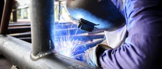
Gas burner flame.
In no case should there be a source of heat or direct sunlight in the rooms where cylinders are stored.
How to obtain welding oxygen: this is done quite simply - from atmospheric air using specialized equipment.
Oxygen is divided into three types based on purity:
- premium grade with a gas concentration of 99.5%;
- first grade with 99.2%;
- the second – with 98.5%.
Acetylene
This is the second most popular gas used in gas welding for both welding and cutting. It is also colorless and odorless. Acetylene may explode if pressurized or heated. It is made from calcium carbide and water.
Acetylene is not the cheapest gas, but its advantages make it very popular among welders. It's all about the combustion temperature - it is remarkably high for acetylene, especially in comparison with cheaper gases such as methane, propane or kerosene vapor.
Flux and filler wire
These are the main participants in the process of weld formation. The filler wire must be absolutely free from the slightest signs of dirt or corrosion. Sometimes, instead of wire, you can use a strip of the same metal as the workpiece for welding.
Fluxes are necessary to protect the weld pool from the harmful effects of external factors. Most often, borax and boric acid are taken as components of flux mixtures, which can be applied directly to the workpieces being welded or to the filler wire.
The only metal that can do without a flux mixture is carbon steel. Well, a special need for the presence of flux arises when welding copper, aluminum and their alloys.
Other popular gas welding methods
- Welding using baths.
The principle of operation is directly reflected in the name of the method - as the work progresses, more and more new weld pools are formed. When one of them occurs, the end of the filler rod is lowered into it. It liquefies there, and then plunges into the reducing portion of the flame. At this time, the nozzle is moved further along the seam - to where the next bath will be formed. Each of them is carried out as if overlapping, overlapping the previous one by about a third of the diameter of the filler material.
This gas welding method is widely used for fillet brazing of pipes made of low-alloy steel or low-carbon alloys, as well as when working with thin metal plates.
- Welding using a through bead.
The welding operation is as follows: first, the metal structural elements are installed in a vertical plane so that between them there is a gap equal in width to half the thickness of the sheet. Then the nozzle moves evenly along the groove, melting the upper edge of the workpiece hole. At the same time, a layer of molten metal is applied to the lower part of the furrow. In this case, a scar is formed in the form of a roller, which connects the structural elements. The seam is dense, without slags and pores.
Lecture on the topic: "Gas welding technology"
LECTURE No. 1.4. TOPIC: “GAS WELDING TECHNOLOGY”
Content:
Gas welding technique
Gas welding technology
Features of welding various seams
Special types of gas welding.
1. GAS WELDING TECHNIQUE.
Left and right welding.
Torch position for gas welding. The choice of welding method depending on the position of the seam in space. Special types of gas welding. Bevel methods.
In practice, there are two methods of manual gas welding: right and left. The left-hand method
of gas welding (Fig. 1, a) is a method in which welding is carried out from right to left, the welding flame is directed to the edges of the metal that have not yet been welded, and the filler wire is moved in front of the flame.
The left method is the most common and is used when welding thin and low-melting metals.
With the left-hand welding method, the edges of the base metal are preheated, which ensures good mixing of the weld pool. With this method, the welder clearly sees the seam being welded, so the appearance of the seam is better than with the right method. welding method (Fig. 1, 6) is a method when welding is performed from left to right, the welding flame is directed to the welded area of the seam, and the filler wire is moved after the torch.
With the right method, the burner mouthpiece performs slight transverse vibrations. Since with the right method the flame is directed towards the welded seam, it provides better protection of the weld pool from oxygen and nitrogen in the air and slower cooling of the weld metal during the crystallization process. The quality of the seam with the right method is higher than with the left one. The heat of the flame is dissipated less than with the left method.
Rice. 1. Welding methods: a - left; b - right Therefore, with the right welding method, the weld cutting angle is not 90°, but 60-70°, which reduces the amount of deposited metal and warping of the product. The right method is more economical than the left one, welding productivity with the right method is 20-25% higher, and gas consumption is 15-20% less than with the left one. The right method is advisable to use when welding parts with a thickness of more than 5 mm and when welding metals with high thermal conductivity. When welding metal up to 3 mm thick, the left method is more productive.
The power of the welding torch for steel with the right method is selected based on acetylene 120-150 dm3/h, and with the left method - 100-130 dm3/h per 1 mm of the thickness of the metal being welded. The diameter of the filler wire is selected depending on the thickness of the metal being welded and the welding method. With the left-hand welding method, the diameter of the filler wire is d=S/2+1 mm, and with the right-hand method, d=S/2 mm, where S is the thickness of the metal being welded, mm.
Left and right welding. When welding on the left (Fig. 2, a
) the torch moves from right to left, and during right-hand welding (Fig. 2,
b
) - from left to right. In the first case, the filler wire is located in front of the burner flame, in the second case, behind it. With the left method, the flame is directed to the unwelded part of the seam; For more uniform heating of the edges and better mixing of the metal of the weld pool, zigzag movements of the tip and wire are performed.
Rice.
2. Welding methods and angle of inclination of the mouthpiece: a - left, b - right; 1 - welding moment, 2 - patterns of movement of the nozzle and wire, 3 - angles of inclination of the nozzle and wire, c - angle of inclination of the nozzle at different metal thicknesses Left-hand welding provides a more uniform height and width of the seam in the welded joint, the highest productivity and lower cost when welding sheets up to 5 mm thick. This is because the flame preheats the base metal to be welded. In addition, left-hand welding is easier to perform and does not require the welder to acquire great skills.
Left-hand welding is also used for low-melting metals. For welding steel using the left method, the flame power is set to 100 - 120 dm3 of acetylene/h per 1 mm of the thickness of the metal being welded. An increase in speed during left-hand welding compared to right-hand welding can only occur as long as the heat absorption by the product (loss) is insignificant, and this is only possible when welding thin sheets.
When sheet thickness is more than 5 mm, left-hand welding is inferior in speed to right-hand welding. In right-hand welding, heating in the weld pool is more intense, more heat is introduced into the weld pool, and the flame core can be brought closer to the surface of the pool. In addition, the flame heats up the already deposited metal, this heating spreads over a small distance from the weld pool, therefore, heat treatment of the weld metal and the heat-affected zone occurs.
With the right-hand method, oscillatory movements of the nozzle are usually not performed, and spiral movements are performed with the filler wire, but with a smaller amplitude than with left-hand welding.
The flame power for welding steel is set to 120 - 150 dm3 of acetylene/h per 1 mm of the thickness of the metal being welded.
2. GAS WELDING TECHNOLOGY
To obtain a weld with high mechanical properties, it is necessary to prepare the welded edges well, select the correct burner power, adjust the welding flame, select the filler material, set the position of the torch and the direction of its movement along the welded seam.
Preparation of edges consists of cleaning them from oil, scale and other contaminants, cutting them for welding and tack with short seams.
The welded edges are trimmed to a width of 20.. 30 mm on each side of the seam. For this purpose, you can use the flame of a welding torch. When heated, scale lags behind the metal, and paint and oil burn out. Then the surface of the parts to be welded is cleaned with a steel brush to a metallic shine. If necessary (for example, when welding aluminum), the welded edges are etched in acid and then washed and dried.
The preparation of edges for welding depends on the type of welded joint, which, in turn, depends on the relative position of the parts being welded.
Rice. 3
Butt joints
are the most common type of connections for gas welding.
Metals up to 2 mm thick are butt welded with flanged edges (Fig. 3, a)
without filler material, or butt welded without cutting edges and without a gap (Fig. 3, b), but with filler material.
Metal with a thickness of 2...5 mm is butt welded without cutting the edges, but with a gap between them (Fig. 3, c).
When welding metal with a thickness of more than 5 mm, V- or X-shaped cutting of edges is used (Fig. 3,
d)
. The bevel angle is selected within 70...90°; At these angles, good penetration of the top of the seam is obtained.
Corner connections
(Figure 3,
e
) are also often used when welding thin metals. Such joints are welded without filler metal. The seam is obtained by melting the edges of the parts being welded.
Lap (
rice.
3, f
) and T
-joints (
Fig. 3, g
are
The edges are beveled using a manual or pneumatic chisel, as well as on edge planing or milling machines. An economical way to prepare edges is by hand or mechanized oxyfuel cutting; The resulting slag and scale are removed with a chisel and a metal brush.
To prevent changes in the position of the parts being welded and the gap between the edges during the entire welding process, the product is secured in fixtures or using tacks. The length of the tacks, their number and the distance between them depend on the thickness of the metal, the length and configuration of the seam being welded. When welding thin metal and short seams, the length of the tacks is 5...7 mm, and the distance between them is 70...100 mm. When welding thick metal and a significant length, the tacks are made 20...30 mm long, and the distance between them is 300...500 mm.
The main parameters of the welding mode are selected depending on the metal being welded, its thickness and the type of product. Determine the required flame power, type of flame, grade and diameter of filler wire, and welding technique. Sutures are applied in single-layer or multi-layer. When the metal thickness is up to 6...8 mm, single-layer seams are used, up to 10 mm, the seams are made in two layers, and when the metal thickness is more than 10 mm, the seams are welded in 3 layers or more. The thickness of the layer in multilayer welding depends on the size of the seam, the thickness of the metal and is 3...7 mm. Before applying the next layer, the surface of the previous layer must be thoroughly cleaned with a wire brush. Welding is done in short sections. In this case, the joints of the rollers in the layers should not coincide. With multilayer welding, the heating zone is smaller than with single-layer welding. During the welding process, when surfacing the next layer, the underlying layers are annealed. In addition, each layer can be forged. All these conditions make it possible to obtain a high-quality weld, which is very important when welding critical structures. However, it should be taken into account that welding productivity is low with high consumption of combustible gas.
Low-carbon steels can be welded using gas welding without much difficulty. Welding is performed with a normal flame. The filler material is welding wire in accordance with GOST 2246-70. Critical structures made of low-carbon steel are welded using low-alloy wire. The best results are obtained by silicon-manganese and manganese wires of the Sv-08GA, Sv-10G2, Sv-08GS, Sv-08G2S brands. They make it possible to obtain welds with high mechanical properties. Specific flame power - 100... 150 l/(h mm).
Medium-carbon steels are welded satisfactorily, however, during welding, hardening structures and cracks may form in the weld and the heat-affected zone. Welding is performed with a slightly carburizing flame, since even with a slight excess of oxygen in the flame, significant carbon burnout occurs. The specific flame power should be in the range of 80... 100 l/(h mm). The left-hand welding method is recommended to reduce overheating of the metal. If the metal thickness is more than 3 mm, preliminary general heating of the part should be carried out to 250...300°C or local heating to 650...700°C. The filler material is the grades of welding wire specified for low-carbon steel and wire grade Sv-12GS.
When determining the flame power, it should be borne in mind that when welding in the right way, the specific power should be increased by 20...25%. Increasing the flame power increases welding productivity. However, this increases the risk of metal burnout.
Filler wire diameter d
(mm) when welding metal up to 15 mm thick using the left-hand method is determined by the formula
d
=
S/2
+1, where S is the thickness of the steel being welded, mm. With the right method, the diameter of the wire is taken equal to half the thickness of the metal being welded. When welding metal with a thickness of more than 15 mm, wire with a diameter of 6...8 mm is used.
After welding, it can be recommended to forge the weld metal in a hot state and then normalize it from a temperature of 800...900°C. In this case, the metal acquires sufficient ductility and a fine-grained structure.
Position of the torch and filler wire during gas welding. The burner flame is directed at the metal of the product so that the edges of the parts to be welded are in the reduction zone of the flame at a distance of 2 - 6 mm from the end of the core. The end of the metal core of the product and the filler rod must not be touched. This will cause carburization of the bath metal and will cause popping and flashback fires.
The rate of heating of metal during gas welding can be adjusted by tilting the torch mouthpiece relative to the metal surface. With increasing metal thickness, the angle of inclination of the burner mouthpiece to the vertical increases (Fig. 3, c
).
The angle of inclination of the filler wire to the metal surface is usually 30 - 40° and can be changed by the welder depending on the position of the weld in space, the number of layers of the multilayer weld and other conditions.
As a rule, the end of the filler wire should always be in the weld pool, protected from the surrounding air by gases - the reduction zone of the flame. It is not recommended to use the so-called drip welding process to form a seam, when the wire is periodically lowered into the weld pool, due to the danger of oxidation of the wire metal at the moment of its separation from the weld pool.
3. FEATURES OF WELDING VARIOUS SEAMS
Horizontal seams are welded in the right way (Fig. 4, a).
Sometimes welding is done from right to left, holding the end of the wire at the top and the mouthpiece at the bottom of the bath. The weld pool is positioned at a certain angle to the axis of the seam. This makes it easier to form a seam, and keeps the bath metal from dripping.
Vertical and inclined seams are welded from bottom to top using the left method (Fig. 4, b). When the metal thickness is more than 5 mm, the seam is welded with a double bead.
When welding ceiling seams (Fig. 4, c), the edges are heated until melting (fogging) begins, and at this moment a filler wire is introduced into the bath, the end of which is quickly melted. The metal of the bath is kept from flowing down by a rod and the pressure of the flame gases, which reaches 100-120 gf/cm2. The rod is held at a slight angle to the metal being welded. Welding is carried out in the right way. It is recommended to use multi-layer seams welded in several passes.
Welding of metal less than 3 mm thick with flanged edges without filler metal is carried out using spiral (Fig. 4, d) or zigzag (Fig. 4, e) movements of the nozzle.
4. SPECIAL TYPES OF GAS WELDING
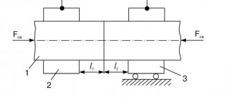
Through bead welding
is performed with the parts in a vertical position in the direction from bottom to top.
The inclination of the torch and filler wire, as well as the nature of the movement of the torch and wire during the welding process are shown in Fig. 5.
Rice. 5. Scheme of welding with a through bead with thickness S: a - from 2 to 6 mm, b - from 6 to 12 mm, c - from 12 to 20 mm
For sheet thicknesses from 2 to 12 mm, the edges are not beveled. Welding begins by melting a hole with a diameter equal to the thickness of the sheets being welded. Then the lower part of the hole is melted with wire over the entire thickness of the metal, the flame is moved, melting the upper part of the hole and applying the metal to the lower edge. Thus, the hole moves upward all the time, melting from below and melting from above. During the welding process, circular movements are made with the mouthpiece. The new circular bath should overlap the previous one by 1/3 of the diameter. Steel sheets welded by this method form a tight seam with better mechanical properties than welding in the lower position.
The burner power is selected at the rate of 60 dm3/h per 1 mm of sheet thickness. When welding sheets with a thickness of more than 6 mm, vertical welding is used simultaneously on both sides. The burner power is selected at the rate of 30 dm3/h per 1 mm of metal thickness.
When welding pipes located horizontally, after assembling the joint (usually on welding tacks located, depending on the diameter of the pipe, in 3 to 6 places at equal distances), welding is carried out in sections, regardless of whether the joint is rotary or fixed. In rotation welding, the welded area is usually at the top and occupies a position between the vertical diameter and the diameter inclined to it at an angle of 45°. Pipes without rotation are welded in sections in the lower, inclined and ceiling positions in compliance with the principle of reverse-stage welding in order to combat deformations.
Welding with baths (Fig. 6, a). The essence of this method is the sequential formation of baths of molten metal and the introduction of several drops of filler metal into them.
Each subsequent bath should overlap the previous one by 1/3 of its diameter. This method is sometimes also called drop welding. It is used when welding metal up to 3 mm thick. Welding along flanged edges (Fig. 6, b). It is used when welding thin metal up to 2-3 mm thick. Welding is carried out without filler material; the torch is given an oscillatory or spiral motion.
Rice. 6. Pool welding (a) and welding along flanged edges (b)
Multilayer gas welding.
This welding method has a number of advantages compared to single-layer welding: a smaller metal heating zone is provided; annealing of underlying layers is achieved when surfacing subsequent ones; it is possible to forge each layer of the seam before applying the next one. All this improves the quality of the weld metal. However, multilayer welding is less productive and requires more gas consumption than single-layer welding, so it is used only in the manufacture of critical products. Welding is carried out in short sections. When applying layers, you need to ensure that the joints of the seams in different layers do not coincide. Before applying a new layer, you need to thoroughly clean the surface of the previous one from scale and slag with a wire brush.
Oxidizing flame welding.
Low carbon steels are welded using this method. Welding is carried out with an oxidizing flame having the composition
To deoxidize the iron oxides formed in the weld pool, wires of the Sv-12GS, Sv-08G and Sv-08G2S grades in accordance with GOST 2246-60 are used, containing increased amounts of manganese and silicon, which are deoxidizers. This method increases productivity by 10-15%.
Welding with propane - butane-oxygen flame.
Welding is carried out with an increased oxygen content in the mixture
in order to increase the flame temperature and increase the penetration and fluidity of the bath. For deoxidation of weld metal, wires Sv-12GS, Sv-08G, Sv-08G2S, as well as wire Sv-15GYU (0.5-0.8% aluminum and 1-1.4% manganese) according to GOST are used.
Research by A. I. Shashkov, Yu. I. Nekrasov and S. S. Vaksman established the possibility of using in this case conventional low-carbon filler wire Sv-08 with a deoxidizing coating containing 50% ferromanganese and 50% ferrosilicon diluted on liquid glass. The weight of the coating (excluding the weight of liquid glass) is 2.8-3.5% of the weight of the wire. Coating thickness: 0.4-0.6 mm when using wire with a diameter of 3 mm and 0.5-0.8 mm when using a wire with a diameter of 4 mm. Propane consumption is 60-80 l/h per 1 mm of steel thickness, b = 3.5, the angle of inclination of the rod to the metal plane is 30-45°, the cutting angle of the edges is 90°, the distance from the core to the rod is 1.5-2 mm, to metal 6-8 mm. This method can weld steel up to 12 mm thick. The best results were obtained when welding steel with a thickness of 3-4 mm. Wire Sv-08 with the specified coating is a full-fledged substitute for more scarce grades of wire with manganese and silicon when welding with propane-butane.
Questions for self-control
1. Name the areas of application of gas welding.
2. What are the advantages and disadvantages of left and right welding?
3. What should be the position of the torch and filler wire for left and right welding?
4. Name the special types of gas welding.
Safety precautions for gas welding
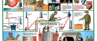
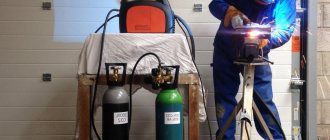
Welding work is particularly dangerous. The use of the gas welding method is no exception. It is worth noting that it requires increased precautions, since welding gases: oxygen and acetylene pose an additional threat. Compliance with safety standards will protect the technician from work-related injuries.
The generator and the gas cylinder must be at least 5 m apart from each other. To avoid damage to the connecting hoses, they must be suspended. If other specialists are also working in the room for gas welding operations, then protective items should be placed around its perimeter.
Before igniting the burner, the hoses are purged: first, the oxygen supply is opened, and then the acetylene supply. Only after this can the flammable mixture be ignited. It is worth making sure that the channels are always clean, otherwise popping or kickback may occur.
Do not operate the welding machine with oily hands or allow the equipment to come into other contact with oil, as this may result in an explosion. If a kickback does occur, it is necessary to promptly shut off the gas supply valves on the cutter, cylinders and water seal. Flames spread slowly through the hoses, but detonation may occur if the specified measures are not taken immediately.
To avoid kickback when working with one of the gas welding methods, it is important to exclude the following factors:
- drop in oxygen pressure - this can occur due to the end of the gas in the cylinder, clogging of the injector or freezing of the reducer;
- the distance from the nozzle to the part is too close - this reduces the gas flow speed;
- excessive heating of the welding tip or pipes;
- clogging of the mouthpiece - this provokes a reduction in the passage opening and, as a result, a drop in the gas flow rate.
If the torch overheats, it is necessary to pause welding work and cool it, for example, in water. An acetylene generator should not be emptied until the gas runs out. Otherwise it may cause backlash.
When performing work using any gas welding method, gas leaks must not be allowed. The most vulnerable places: taps and plugs. You can identify the hole using a soap solution.
Preparation of weld edges for gas welding
Preparation of welded edges includes cleaning them from oil films, paint coatings, scale, dirt and dust, rust, as well as cutting them for welding and tack them with short seams.
Cleaning weld edges for gas welding
Before gas welding, not only the welded edges themselves are cleaned, but also the areas in the immediate vicinity of them. The width of the cleaned area is 20-30mm on each side of the connection.
A welding torch flame works well for cleaning. When heated with a torch, scale moves away from the metal, and paint and varnish coatings and oil burn. After this, the surface of the welded edges and nearby areas is thoroughly cleaned using metal brushes or sandpaper. Cleaning is carried out until a metallic shine appears on the welded surfaces. Often, parts to be welded are shot blasted or sandblasted for cleaning.
In cases where it is impossible to remove contaminants with brushes (for example, when welding aluminum it is difficult to remove oxide films), the welded edges and areas near them are cleaned using special acid-based pastes or etched in acid. After etching, the edges must be washed and dried.
Edge cutting for gas welding
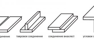
Welded edges are cut depending on the type of welded joint. The type of welded joint is determined by the relative position of the parts being connected. For gas welding, butt welded joints are most typical.
Metals of small thickness (up to 2 mm) are butt welded with flanging of the edges and without the use of filler material (diagram a) in the figure) or without flanging of the edges and without a gap (diagram b) in the figure), in which case filler material is used.
Metal with a thickness of 2mm to 5mm is welded into a joint, without cutting the edges, but leaving a gap between them (diagram c) in the figure). When the thickness of the welded metal is more than 5 mm, a V-shaped or X-shaped groove is used (diagram d) in the figure). The total opening angle of the edges should be 70-90° to ensure good penetration of the root of the weld.
When gas welding metals of small thickness, corner joints are often used (diagram e) in the figure). The gas welding technology for such joints involves welding without the use of filler wire. The formation of a weld occurs due to the melting of the welded edges.
Lap welded joints and T-joints (diagrams e) and e), respectively in the figure), are used only in cases where the thickness of the metal being welded is less than 3 mm. When welding metal of large thickness, as a result of uneven local heating, deformations and stresses occur during welding, which can cause the formation of hot cracks or cold cracks during welding in the weld metal and in the heat-affected zone.
The cutting of edges in welded parts can be done manually, with a pneumatic chisel, on milling machines, or on special edge planing machines. But an economically feasible method is oxygen cutting (manual or mechanized). In this case, scale and slag after cutting must be cleaned to a metallic shine.
Tacking the edges of the parts to be welded before gas welding
Gas welding technology involves tacking parts before welding in order to prevent changes in the position of parts or the appearance of gaps between them during the metal welding process.
The length of the tacks and the distance between them are determined by the thickness of the metal, the shape and length of the weld. When welding parts of small thickness and with a short length of the weld, tacks are made 5-7 mm long at a distance of 70-100 mm from each other.
In the case of welding metal of large thickness and with long weld lengths, the length of the tacks is 20-30mm, and the recommended distance between the tacks is 300-500mm.