To make a high-quality casting, it is not enough to simply melt the metal, pour it into a mold prepared in advance and let it cool. This will result in a product of low strength, with uneven surfaces. To avoid this, injection molding is used. The technology is based on the use of industrial equipment, which creates a working environment for the production of high-quality castings.
Metal smelting
Types of injection molding
Load casting is an efficient way to produce metal parts with complex shapes. Molten metal is filled into a special chamber, which is designed to compress the material. As the pressure rises, the molten mixture fills the metal mold at high speed. The compression chamber can maintain the melting temperature of the material up to 450 degrees. There are three types of technological process depending on the filling speed of the metal structure:
- Low speed - up to 2.5 m/s. The technology is used to produce parts with thick walls.
- Average speed - up to 15 m/s. The metal fills the mold with turbulent movements. The center of the casting is filled with air bubbles, which are removed under the influence of heavy loads.
- High speed - more than 30 m/s. The molten material is fed at such a speed that it is sprayed over the surface of the machine. This traps a large amount of air, which degrades the strength of the casting. To remove air, high loads are pumped - about 500 MPa.
Load casting is carried out by machines with hot and cold chambers.
Types of High Pressure Casting Equipment
Injection molding machines come with a hot (piston and compressor) or cold (piston) pressing chamber. Piston machines can have a vertical or horizontal compression chamber. Three schemes and, accordingly, three types of injection molding machines have become widespread:
- with a cold horizontal pressing chamber;
- with a cold vertical pressing chamber;
- with a hot vertical pressing chamber.
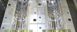
Rice. 1. Scheme of injection molding on machines with a cold horizontal chamber : a - pouring metal into the pressing chamber; b - filling the mold with metal; c - separation of the mold halves; g - pushing out the casting
In machines with a cold horizontal chamber (Fig. 1), the mold consists of a fixed 6 and movable 4 halves. The first is attached to the stationary plate 7 of the machine, and the second is attached to the movable plate 1. Molds may have channels 5 for water cooling. Rods 3 (metal) for forming cavities and holes in castings are, as a rule, located in a movable half-mold. To remove the casting from the mold, ejectors 2 are provided, which are rigidly fixed in the ejector plate.
The locking mechanism of the machine reliably presses the movable half-mold against the stationary one, after which a portion of the alloy is poured into cylinder 8, called the pressing chamber, through hole 13 and the pressing mechanism is turned on. The plunger 9 closes the filling hole and creates pressure in the chamber. The alloy fills the mold cavity through the sprue slot and hardens.
As soon as the casting hardens, the movable part of the mold, together with the casting, is withdrawn. Together with the movable part of the mold, plunger 9 moves, which pushes the press residue 10 out of the pressing chamber. The pusher plate moves along with the mold until it stops 11. The stop stops the pusher plate, and the mold continues to move. The ejectors “remove” the casting 12 from the rod 3, and it falls onto the conveyor or into the container. The mold is blown with compressed air, the working surface is lubricated, closed, and the process is repeated.
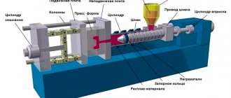
On the bed there is 1 machine with a cold horizontal pressing chamber, models 711A06. . . 71119 (Fig. 2) along the guides 3 under the action of a self-braking lever system 4 driven by a hydraulic cylinder 2, a movable plate 6 with a hydraulic ejector 5 moves. The movable part of the mold 7 is installed on this plate. The fixed part of the mold 8 is installed on a fixed plate 9 with a pressing chamber 10, into which a portion of the alloy is poured, driven into the mold by the press piston of the cylinder 11.
Rice. 2. Diagram of an injection molding machine with a horizontal cold chamber
The locking mechanism of the mold must ensure its reliable retention in the closed state. The locking force of machines with a cold horizontal pressing chamber is 1000. .35,000 kN. Often the locking mechanism is built on the basis of powerful lever self-braking systems.
In Fig. Figure 3 shows a machine model 711A08 with a cold horizontal pressing chamber with a mold locking force of 2500 kN. It has a moving plate stroke of 450 mm and a mass of the poured portion of aluminum alloy of 4.7 kg. The highest no-load speed of the pressing plunger is at least 5 m/s.
Rice. 3. Model 711A08 injection molding machine
The design of the machine provides the ability to connect an automatic manipulator for pouring metal, manipulators for lubrication of the mold and removal of castings, devices for controlling the removal of castings and lubrication of the press plunger, as well as controlling the rods installed on the movable and stationary half-molds according to a given program. The control system is implemented on a relay element base or on the basis of a programmable controller.
When using a scheme with a cold vertical chamber (Fig. 4), a dose of alloy 4 is poured into the lubricated vertical pressing chamber 5. When moving down, the plunger 3 presses on the alloy and together with it moves the heel 2 down, as a result of which hole 1 opens, connecting the pressing chamber with mold cavity. Molten metal under pressure fills the cavity. After filling the mold, the plunger rises up, and a special mechanism raises the heel 2 The heel cuts off the sprue and raises the press residue.
The CLV 100.01 injection molding machine with a vertical cold pressing chamber from VIHORLAT (Slovakia) with a mold locking force of 1000 kN is shown in Fig. 5. When removing the casting, it develops an ejector force from 5.5 to 70.75 kN with a hydraulic ejector stroke of 80 mm. Molten metal injection force from 54 to 178 kN. The injection piston stroke is 270 mm.
Up to 1.3 kg of aluminum can be poured into a feed chamber with a diameter of 80 mm. The time of one idle cycle is 6.5 s.
Machines with a vertical cold chamber differ from those previously discussed in their smaller overall dimensions, but have a longer cycle and approximately 20% lower productivity.
Rice. 4. Scheme of injection molding on machines with a cold vertical chamber : 1 - electrical cabinet; 2 — control panel; 3 - movable plate; 4 - fixed plate; 5 - power cylinder of the press plunger
Rice. 5. Vertical cold chamber injection molding machine
Rice. 6. Scheme of injection molding in machines with a hot vertical chamber
Machines with a hot vertical pressing chamber (Fig. 6) have a furnace 8 with a cast iron crucible 2, in which alloy 3 is maintained in a liquid state by an electric heater 7. The pressing chamber 6 is integral with the crucible. When the press plunger 4 is raised, the chamber is filled with alloy through hole 5. When moving downwards, the press plunger closes hole 5 in the pressing chamber and the alloy under pressure fills mold 1.
A block diagram of a machine with a hot vertical chamber is shown in Fig. 7. On the frame 1, along the guides 3, under the action of a self-braking lever system 4, driven by a hydraulic cylinder 2, a movable plate 6 with a hydraulic ejector 5 moves. The movable part of the mold 7 is installed on this plate. The stationary part of the mold is installed on the fixed plate 9 8 with a channel of the gating system for supplying molten metal. Pressing chamber 13 is connected through hole 14 to a bath of metal molten in the crucible.
Rice. 7. Diagram of injection molding machine with hot vertical chamber
When lowering the press piston 12 using cylinder 11, a portion of the alloy is driven through channel 10 into a closed mold 7-8. After the metal has cooled, the mold is opened, the casting is sent for further processing, and the mold is cleaned, lubricated, and closed. The filling cycle repeats.
A machine with a vertical hot chamber for injection molding IPZ 300 from Italpresse (Italy) is shown in Fig. 8. Like the one shown in the diagram, it includes a furnace 1 for melting metal in a crucible 2, a press plunger 3, a high-pressure cylinder 4 for controlling the press plunger, a fixed plate 5 and other components necessary for operation.
The 713A05M machine automatically blows, lubricates and locks the mold, injects metal, waits for the casting to crystallize, opens the mold, and pushes out the casting. The weight of the poured portion of zinc alloy is 1.8 kg. The idle cycle time is no more than 3 s. It does not require the use of special filling and dosing units.
Areas of application
The technological process of casting under loads makes it possible to obtain castings with a high strength index. Due to the high pressure, air bubbles come out of the product, which has a positive effect on the mechanical properties of the material. Application of this technology:
- production of carburetors for cars;
- creation of plumbing parts;
- production of parts for household appliances.
Load casting is used in the manufacture of parts for computers and various electronics.
Advantages and disadvantages of the method
Any technological process has both strengths and weaknesses. Advantages of injection molding:
- Changing casting properties. The parameters of strength and hardness of the material increase.
- Ability to use casting molds several times in a row.
- The surface quality of the product improves.
- High accuracy of compliance with the established dimensions of castings.
- Possibility of creating thin-walled products (less than 1 mm).
- There are no additional processes of assembly, disassembly, or knocking out finished parts from molds.
- Modern equipment allows you to regulate the rate of flow of molten metal.
Disadvantages of the process:
- Pouring structures wear out quickly if they are frequently exposed to high temperatures.
- It is extremely difficult to manufacture products with holes, recesses, and cavities.
- As the product cools, it gains internal stress.
- It is impossible to create large-sized workpieces, since the equipment is limited in power.
When working with injection molding machines, we must not forget that with this technology the material is filled with air inclusions. This impairs its strength and promotes rapid destruction. You can get rid of air bubbles by increasing the load. However, this requires powerful equipment.
Size and weight of castings
Features of products in RIM technology
The following is a brief overview of the key factors, from wall thickness to draft radius, that the designer and engineer must consider when modeling injection molded products.
Wall thickness: The most important criterion for obtaining good quality castings is uniform wall thickness. Thus, the likelihood of receiving deformed or warped products is minimized.
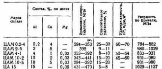
| Wall thickness | |
| Material | Recommended Wall Thickness (inch) |
| ABS | 0,045-0,140 |
| Acetal | 0,030-0,120 |
| Acrylic fiber | 0,025-0,150 |
| Liquid crystal polymer | 0,003-0,120 |
| Long fiber reinforced plastic | 0,075-1,000 |
| Nylon | 0,030-0,115 |
| Polycarbonate | 0,040-0,150 |
| Polyester | 0,025-0,125 |
| Polyethylene | 0,030-0,200 |
| Polyphenylene sulfide | 0,020-0,180 |
| Polypropylene | 0,025-0,150 |
| Polystyrene | 0,035-0,150 |
Note: These are general data and may vary depending on product geometry. Large products should not have a minimum wall thickness. Prototyping laboratories use a wall thickness of 0.040-0.140 inches as the standard.
Geometry of the sign: reduce the central part of the product to prevent the formation of thick walls. The functions of the sign remain the same as in the traditional injection molding process. Excessive thickness can change the dimensions of the product, reduce strength and make subsequent machining mandatory.
On the left is the original model of the product. On the right is a model of a product whose thickness has been reduced, while maintaining its functionality.
Slopes: Avoid sharp transitions that cause residual stress.
Rounding: build in parts that support themselves.
Rounding: Sharp corners weaken parts and create residual stress from the flow of plastic. Sharp corners must be rounded.
Ribs: to avoid the appearance of sink marks, the ribs should make up no more than 60% of the wall thickness.
Bushings: Do not create bushings with thick walls, they can lead to the formation of sinks and voids in the product.
The bushings on the left have too thick walls that will not be filled and voids will form. The bushings on the right provide plenty of strength without thick walls.
Taper: Taper (sloping vertical walls) makes it easier to remove items without leaving pull marks or push marks. Taper also makes it possible to increase depth, reduces tool vibration and reduces the risk of cosmetic defects when milling walls. If possible, use a slope of at least 1 degree. When designing the die and punch - a minimum of 2 degrees, sliders - 1 degree for every 2 inches of depth. At 2-4 inches deep, 3 degrees or at least 1/8 inch thickness will be needed.
Die-Punch: When designing, use a die and punch instead of ribs. This will ensure uniform wall thickness instead of thickening at the base. It also improves the surface appearance and increases production speed.
Undercuts : An undercut is a part of a product that overlaps another part of the product, creating an obstruction between the product and one or two halves of the mold. The picture below left (1) shows a lock with an undercut. In the picture on the right (2), the undercut hole allows the plastic injection mold to pass through the product and maintain the product's latch shape.
Side gussets: Side gussets create undercuts on the outside of the product. The undercuts must be on or connected to the parting line. They must also be in the plane of the parting line, connected and perpendicular to the direction of opening of the mold.
The blue part is the side A-insert.
Elastic deformation: This is a small undercut in the design of a product that allows the product to be removed from a conventional mold without the use of side inserts. Elastic deformation can be a solution for small undercuts, but the geometry of the product and the material used must be taken into account.
The green part is the part with elastic deformation.
Embeds: This is a separate piece of metal that is inserted into the mold to create an undercut. It is ejected along with the product and then manually separated by the operator and reinserted into the mold. Using embeds allows designers to bypass shape and placement restrictions, but is more expensive to use than using side inserts.
Steel signs: Holes can be made using steel signs in a mold. The steel sign is strong enough to withstand the stress of being pulled out and has a surface smooth enough to be removed without leaving a pull mark. There will be no cosmetic defects on the final product, and if there are any, they will appear on the inside of the hole, where they are not visible.
Logos and text: textured surfaces, numbered parts, company logos - all this looks good, but you must be prepared to pay for these and other features that are not related to the main function. However, product numbering is a mandatory requirement, for example in the aerospace and military sectors. When it comes to text, designers recommend the following:
- Use easy-to-render fonts (grotesque fonts) such as Century Gothic Bold, Arial, or Verdana.
- The font size must be at least 20.
- The depth should not exceed 0.010-0.015 inches.
- Be prepared for increased draft angles when pushout is an issue.
Slotted gates: The thin lip restricts the flow of melt and can break when the gate is pulled off. The slotted sprue allows you to make the junction with the product thicker.
Mating parts: identical parts that separate and connect, saving on a second mold. Mating elements may include pins and holes, connecting edges, hooks and latches.
Tolerances: Designers typically maintain an accuracy of ±0.003 inches. Shrinkage tolerances depend primarily on the design of the product and the choice of plastic. They can range from 0.002 inches for stable plastics like ABS and polycarbonate to 0.025 inches for unstable plastics like TPR. There are different technologies that allow you to achieve maximum accuracy.
Low pressure casting technology
Another method of casting involves the use of low pressure. This technology has certain advantages:
- Possibility to produce products of large sizes, with thin walls.
- Less material is spent on the gating system.
- Low pressure does not have a destructive effect on the walls of the mold or working elements of the equipment.
- The high feed rate of molten metal allows the production of large-sized hollow parts.
Most often, low-load casting technology is used in ferrous metallurgy.
Equipment
When the technological process is carried out, two types of injection molding machines are used:
- With a hot camera. Used to create castings from metals that melt at temperatures up to 450 degrees Celsius. The design is designed in such a way that during the working stroke of the piston, through which pressure is transmitted, the molten metal itself fills the mold. When it is filled to the brim, a sensor is triggered, transmitting a signal to the piston. He starts moving down. After the material crystallizes, the mold opens automatically. Movable mechanisms push the casting out. The equipment operates under difficult conditions. Because of this, various machine parts often fail.
- Machines with cold chambers. A small pressure is applied (up to 100 MPa). The master must pour the molten material into the chamber, which is intended for pressing. Then, under the influence of loads, the future product is sent to the mold. The metal crystallizes. After this, the moving elements open the structure to harden. The rod is removed from the workpiece, leaving a free cavity. The press pushes the product out.
Machines with cold chambers do not allow the production of thin-walled parts due to the rapid cooling of the material.
Injection Molding Machine
Features of the technological process
This process uses special steel molds designed to pour molten material, which under high pressure crystallizes into a given configuration.
This device is a casting equipment, the design of which includes moving and stationary parts. The former move along guide cylinders, the latter are mounted on a stationary plate.
Before the start of the technological process, the moving part of the mold is tightly fixed to the stationary parts using a hydraulic cylinder. Then, to prevent the movement of these parts, the latter are secured using special locks. After the molten material is poured and solidified, the moving part of the device is moved to the side. The workpiece obtained under high pressure is removed from the equipment using mechanical pushers.
Before starting the process, internal parts that come into contact with the molten material are pre-treated with a special release agent. This composition is used to eliminate the negative impact of high temperatures on steel parts of equipment and to smoothly separate the created workpieces from the walls.
Injection molding is carried out automatically using industrial installations. The main unit of this equipment is the chamber in which the material is pressed. This structural element comes in two types: cold and hot. Structurally, the first chamber is presented in the form of a horizontally laid cylinder, inside of which there is a piston and a funnel used for pouring molten material.
The process of manufacturing parts in such equipment comes down to the following: after filling the installation with metal, the piston is started, which, moving inside the cylinder, pumps the melt into the mold. After filling the latter, the pressure inside the chamber increases. This occurs due to increased force on the piston, which leads to crystallization of the metal.
The hot chamber of the molds is presented in the form of a bath located in a cast iron crucible, which is constantly heated during the creation of blanks. Such installations also use a piston, which, when moving, pushes the melt out of the crucible. Next, the metal rises through a special channel with a heated mouthpiece (prevents hardening of the material), through which it enters the mold. At the end of the process, the remaining melt is returned to the bath.
Molds with a hot chamber are used to create blanks from zinc and magnesium alloys.
Material heating temperature
The temperature to which the material is heated is selected taking into account two parameters: the grade of the alloy and the geometric parameters of the part being created. Failure to comply with this rule leads to serious consequences. Due to overheating of the material when filling the mold, splashes fly out, blocking the ventilation holes, as a result of which gas removal is disrupted, which leads to the appearance of pores in the workpiece after the latter has hardened.
Exceeding the permissible temperature leads to an increase in the duration of metal crystallization, which is why it takes more time to complete the technological process. This leads to increased load on the equipment, which increases mold wear. Under such conditions, the risks of metal welding to the internal walls increase. As a result, the likelihood of damage to the part during ejection increases.
This technological process involves performing pressing at a minimum temperature. Non-ferrous metals can be heated 10-300 degrees above the point at which the alloy begins to harden. Moreover, if the technical specifications require the production of parts with a thin wall, the heating temperature increases. When creating castings of a simple configuration, the reverse approach is used. In such cases, the material is heated to a temperature slightly above its melting point.
If high-strength parts are manufactured during this technological process, then the metal is poured into a mold in a solid-liquid state. This approach allows you to achieve the following results:
- eliminate the appearance of a shrinkage effect in the created workpiece;
- reduce the negative impact of high temperature on equipment;
- reduce the duration of the casting solidification process;
- reduce the risk of metal welding to internal walls.
Metal with inclusions of the solid phase is pressed exclusively in installations with a cold chamber. This is explained by the fact that when manufacturing parts from this material in other equipment, the risk of melt solidification in the supply channel increases. In particular, during aluminum injection molding, the volume of solids should be 40-60%, provided that the mold is filled smoothly and the quality of the casting remains at a high level.
Molten material feed rate
The speed at which the piston compresses the molten material is determined taking into account the characteristics of the alloy and the geometry of the part being manufactured:
- The part is simple in shape and has thick walls. In this case, rapid pressing of the melt is not required.
- A part with a complex geometric shape and thin walls. When creating such a workpiece, the melt is pressed at high speed. This requirement is explained by the fact that the liquid material must have time to fill all the cavities before solidification begins.
Exceeding the permissible pressing speed leads to the fact that the supplied jet scatters into small droplets, as a result of which air enters the melt. If the design provides for an insufficient number of channels intended for the removal of gases, or if they are clogged, voids will remain in the cast workpiece. To avoid such consequences, injection molding is carried out in a vacuum in which the mold is placed.
The speed at which pressing is carried out determines the quality of the castings and the service life of the equipment. If the melt is fed too quickly, the lubricant used to treat the bath will be washed away. Because of this, the metal sticks to the inner walls, which, when pushed out, leads to damage to the workpiece.
If the speed is too slow, the quality of the part will deteriorate. In this case, the metal begins to harden until the pressure inside the equipment is increased. To avoid the described consequences, the molten material is fed into the mold at a speed of 10-50 m/s. A smaller parameter is selected when creating workpieces from steel and copper alloys. Molten tin and zinc are fed at a faster rate.
Pressure on the melt during solidification
After filling the mold with metal, the pressure on the piston increases many times over. The material experiences this impact until it hardens. Thanks to pressure:
- the density of the workpiece increases;
- the mechanical characteristics of the casting are improved;
- the formation of shrinkage defects is eliminated;
- the quality of casting improves;
- the risk of marriage is reduced;
- The surface cleanliness of the metal part increases.
The pressing force is determined depending on the requirements for the strength characteristics of the part: the higher the second parameter, the greater the pressure should be. This indicator also depends on the type of alloys:
- aluminum ones are pressed under pressure of 40-200 MPa;
- based on magnesium - 40-180 MPa;
- zinc - 10-50 MPa.
The thicker the wall of the part being manufactured, the higher the pressure during crystallization should be.
Mold heating temperature
Before feeding the melt, the mold is heated to a temperature determined depending on the type of alloy and wall thickness:
- zinc - 120-1600 degrees;
- based on magnesium - 200-2400 degrees;
- aluminum - 180-2500 degrees;
- based on steel - 200-2800 degrees;
- brass - 280-3200 degrees.
When producing parts with thin walls, the mold is heated to the upper limit of the indicated ranges, with thick walls - to the lower limit. This is due to the fact that in the first case, this approach makes it possible to prevent the solidification of the metal before filling the mold, and in the second, it increases the rate of solidification of the material.
Technical process
Metal injection molding has several stages that must follow strictly one after another. If the technology is broken, the result will not correspond to the norm. Stages of work:
- A mold is made to create castings.
- It is attached to the car.
- The metal is melted and fed into the pressing chamber.
- Under the influence of increasing loads, it is poured into the mold at high speed.
- Next, the material crystallizes, and at the same time the working piston begins to act on it.
- When the product is ready, the holding structure automatically opens. Moving elements push parts out of the machine.
Automated equipment requires the master to control moving elements and check workpieces. The manufacture of structures for creating castings of complex shapes requires accurate drawing up of drawings and the use of high-strength alloys and metals. They must withstand loads exceeding 500 MPa.
Die casting is a technology that allows the production of metal products with thin walls. Used in various industries. It is important to know the main stages of the technological process, take into account the material used, and the capabilities of the equipment. High loads can damage the machine and damage the metal structure.
Main areas of our activity
Design and production of molds for casting and blowing
We produce molds of any complexity for injection molding of polymers, for extrusion blow molding, for blowing PET containers. Along with the production of molds/equipment for any purpose, we have a number of specializations
, which have accumulated many years of experience and extensive interaction with our regular customers. Among them:
Injection molds
— PET preforms
in a wide range of types, weights and purposes;
— disposable cutlery
(forks, spoons, knives, stirrers);
— closure elements
(stoppers, lids, caps, handles, valves, auxiliary and decorative elements for them);
- stationery
(vertical and horizontal trays, pencil holders, jars and boxes for gouache and watercolor paints; -
components for building finishing and decoration
(corners and connectors for PVC skirting boards, plugs, overlays, etc.); -
body parts of arbitrary designs
, including transformable ones, to obtain an assortment range on one form using form-building replaceable parts.
Blow molds
— from PET preforms
(bottles, including those with a side handle, cans, kegs, etc.) for bottling and packaging: water, carbonated drinks, beer, alcohol, juices, dairy products, vinegar, vegetable oils, sauces, syrups, honey, bulk: tea, spices, salt, household and automotive chemicals, technical.
liquids, detergents (except alkaline solutions), cosmetics, varnishes, paints, medications, etc.; - made of polyethylene, polypropylene, etc.
(bottles, jars, flasks, canisters of all types) for bottling and packaging: milk, kefir, ketchup, mayonnaise, detergents and cosmetics, household and auto chemicals (including alkali-containing solutions), creams , machine oils, paints and varnishes, medicines, bulk products, etc.
Equipment supplies
We supply special equipment and peripherals for casting, extrusion, blow molding, recycling, its technical support and service, and provision of spare parts from a hot warehouse.
Manufacturing Services
We offer our plastic molding services at our site in Minsk for mold customers who do not have their own polymer processing cycle. In this case, clients, on a contractual basis, transfer the manufactured technological equipment to us for safe storage and operation, do not bear any costs or risks for routine (including post-warranty) maintenance, pay only for the finished product at a pre-agreed price, agree on a schedule for the production and delivery of goods parties.
Development of the serial production direction
We have launched a new project to produce plastic products developed under the PTL brand.
About Plastic Technologies