CASTING DEFECTS AND THEIR CORRECTION
Any violation of technology is the cause of defects in castings. Casting defects, even at advanced factories, amount to 2–5%, and sometimes reach 10–20% of the number of castings produced. As a result, the national economy suffers huge losses. Foundries have special reject areas where castings with defects are received daily. These castings are carefully examined and, with the participation of craftsmen, technologists and those responsible for the defect, the reasons for its occurrence are analyzed; Here they also determine measures to prevent defects and check the implementation of previously planned measures. All foundries carry out technological and organizational measures to study the causes of the main types of defects and eliminate them.
Classification of casting defects
The most common casting defects can be divided into four groups:
1) external defects detected directly on the surface of the casting (discrepancy between dimensions and weight as specified, welds, floods, misalignment, underfilling, etc.);
2) volumetric defects located inside the casting and violating its continuity (hot and cold cracks, gas and shrinkage cavities, etc.);
3) discrepancy between the chemical composition and structure of the casting;
4) unsatisfactory mechanical properties.
Internal defects
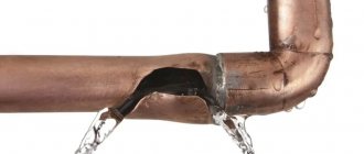
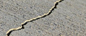
Hot or cold cracks
Hot cracking is caused by using the wrong type of filler rod. The metals of the part and the electrode must be compatible.
The second reason may be an incorrect attempt to seal the crater. If, when correcting this defect, the impact is abruptly interrupted, the seam may crack.
Cold cracks appear after the seam has cooled. If it is made poorly, then when it hardens, the canvas may burst. Or if the connection is subjected to a mechanical load exceeding its resistance level.
This type of defects can also appear on the surface of the canvas, which partially refers to it as external defects.
Pores
Joint porosity is quite common. Pores inside the weld body can form when the working area is poorly protected from oxygen exposure, or the metal preparation stage is ignored or carried out incorrectly.
If there is rust left on the edges of the joint, there are any inclusions that disrupt the uniformity of the seam. Like cracks, pores can be an internal or external problem.
To avoid the appearance of porosity in the seam, you need to make sure that the supply of protective gas is configured correctly and protect the working area from external influences that could disrupt the protective cocoon (drafts, gusts of wind).
And also carry out the preparatory stage correctly.
CASTING QUALITY CONTROL
External inspection of castings is carried out in two stages: first before cleaning and annealing, and then after final cleaning.
The chemical composition of castings is determined by chemical or spectral analysis. A sample for chemical and spectral analysis is usually a sample cast to the castings or a sample for mechanical testing.
The geometric dimensions of castings are controlled using templates, special devices and markings on the slab. Dimensional deviations should not exceed the permissible limits.
The mechanical properties of gray iron castings are monitored by determining tensile strength and Brinell hardness. When testing ductile iron, tensile strength, elongation, Brinell hardness and, in some cases, impact strength are determined. For steel castings, tensile strength, elongation, taper and hardness are determined from samples turned from the workpiece. Castings from non-ferrous alloys are tested for tension, elongation and hardness.
The structure of the metal of castings is determined by examining the fracture of samples or specially prepared specimen-sections with the naked eye (macroscopic analysis) or with a metallographic microscope at a magnification of 100 to 500 times (microscopic analysis).
Defects in castings (cracks, holes, looseness) can be detected using a magnetic method, X-ray and gamma ray scanning, and leak testing.
The magnetic testing method is based on the fact that a pre-magnetized casting under test is placed between the poles of an electromagnet or in the magnetic field of a solenoid through which current is passed. If such a coil is moved along a magnetized casting, then when it encounters any defect (crack, hole), the direction of the magnetic current changes and an induced emf appears in the turns of the coil, measured by a galvanometer.
In another magnetic method of detecting defects, the magnetized casting is coated with dry powder (powder method) or wetted with a liquid magnetic emulsion (emulsion method). Small castings are sometimes placed in a bath of magnetic emulsion. The powder applied to the surface of the casting is collected at the location of the hidden defect and thus reveals its boundaries. The casting is then demagnetized.
Inspection of castings by X-rays is carried out using special X-ray installations (Fig. 169). An X-ray tube is a glass vessel in which residual pressure is created. A high voltage source of 110–220 kVA is connected to electrodes 1 and 2. The filament transformer heats the cathode. Under the influence of an electric field, electrons from the cathode rush to the anode and create electron oscillations on the inner electron shells of the metal atoms of the anode. These vibrations produce short electromagnetic waves called X-rays. X-rays from the anode are directed to the casting 4. Internal defects 5 (cracks, cavities, looseness) reduce the actual thickness of the casting body (H>H1 + k), through which the X-rays pass, therefore their absorption by different parts of the casting is different. Where the rays pass through a hole or crack, their absorption by the casting will be less, therefore on photographic plate 6 the location of the hole, looseness or crack will be revealed by a spot repeating the outline of this defect.
Gamma ray transmission makes it possible to detect internal defects in thick-walled castings. Gamma rays are produced by the emission of radioactive isotopes. For scanning castings, the most common installations are those with radioactive Co, which, however, provides high-quality images only when inspecting castings with a thickness of more than 30 mm.
The casting is checked for tightness by hydraulic or air testing. During hydraulic testing, the holes in the casting cavity are closed with plugs. Water is used as the liquid. The pressure during hydraulic testing is prescribed depending on the operating conditions of the part. The outer surface of the casting must be dry, otherwise it is impossible to detect traces of leakage.
In an air test, pressurized air is supplied inside the casting, and the casting is placed in water. Sometimes the surface of the casting is covered with a soap solution; In the event of a leak, bubbles appear on the surface of the castings, indicating the location of the leak.
Oxidation and hydrogen saturation
As a result of the continuous oxidation of the aluminum melt and its saturation with hydrogen, the following defects arise in the aluminum casting, which are the causes of defective finished castings:
- pores;
- air saturation;
- inclusions;
- violation of tightness;
- surface defects;
- low strength;
- low plasticity.
To prevent or reduce the effects of oxidation and hydrogen saturation, the following measures are taken:
- metal processing in a furnace and its degassing;
- strict control of melting and casting temperatures;
- filtering the melt.
When aluminum transitions from a liquid to a solid state, hydrogen dissolved in it is released and, in interaction with oxides, creates porosity problems in finished castings.
The main task in ensuring high quality aluminum melt is maintaining the oxidation rate of the melt within certain limits. To do this, the following actions are taken:
- high quality of raw pigs;
- modern foundry equipment and casting technologies;
- control of charge loading (dry charge, rapid melting);
- temperature control during melting and casting;
- melt cleaning and melt quality control;
- safety measures during processing and transportation of the melt and its casting.
REASONS AND PREVENTION MEASURES FOR DEFECTS
A discrepancy between the dimensions of the casting and the drawing may be the result of incorrectly assigned shrinkage during the manufacture of the model kit, as well as inaccurate assembly of the mold. This defect can be eliminated by fine-tuning the model kit and increasing the accuracy of the mold assembly.
A discrepancy between the mass of a casting and the one specified in the drawing most often occurs for the same reasons as a discrepancy in dimensions. In addition, an increase in mass is possible due to deformation of the mold when pouring it with liquid metal.
Spills and underfills (Fig. 170) in castings are formed from unfused metal flows that have lost their fluidity before the entire mold is filled. Such flows are obtained when filling a mold with insufficiently superheated metal through feeders of small cross-section, with an excessively wet molding sand (in thin-walled castings) or insufficient gas permeability of the molding sand.
Fills on a casting usually occur along the mold joint due to wear of the flasks, their warping, and also due to poor fastening of the mold.
Misalignment in castings occurs when the mold is assembled carelessly as a result of displacement of the mold half or incorrect alignment of the flasks, due to wear of bushings and pins, or mismatch of the symbolic parts of the rod on the model and in the core box. The casting is obtained with offset parts.
Burnt-on is a strong connection of the surface of castings with the molding or core mixture, which is formed due to insufficient fire resistance of the molding materials, their contamination with harmful impurities, poor quality of foundry paints, and insufficient compaction of the mold.
Dents are narrow and long dents in the body of the casting, covered with a layer of metal, separated from the body of the casting by a layer of molding material. They usually form on large flat surfaces of castings, especially when the raw molds are strongly compacted. Zhimins (Fig. 171) appear due to the thermal effect of liquid metal on the walls of the mold, as a result of which the surface layers of the latter are heated and deformed, forming a dent on the casting. Sometimes the deformations of the surface layer of the mold are so great that its surface crust peels off, forming a crack into which the melt gets trapped.
To prevent the formation of cracks, you should not overcompact the mold, fill it with metal at a given temperature, increase the speed of pouring the metal, use special penetrating coatings that strengthen the surface of the mold, preventing the occurrence of cracks in the mold when heated by the metal. Squeezing can be eliminated by applying marks (in the form of a grid of intersecting lines) on the surface of the mold with a lancet or by making special anti-squeezing ribs on the model. The risks reduce the deformation of the surface of the molds and prevent it from peeling.
Hot cracks occur in castings at a high temperature of the metal being poured, increased shrinkage of the casting, improper design of the gating system and profits, poor compliance of the rod, mold, incorrect design of the castings, uneven cooling, causing internal stresses in the casting, as well as when the chemical composition of the metal deviates from given. Hot cracks have a dark oxidized surface.
Cold cracks can be the result of both uneven shrinkage of individual parts of the casting, and simply mechanical damage during knocking out and cleaning. Cold cracks have a light metallic, non-oxidized surface. To eliminate cold cracks, it is necessary to ensure uniform cooling of the casting in thin and thick areas.
Gas shells are voids in the body of a casting that have a clean and smooth surface. They can be open (external) or closed (internal) and occur when there is excessive gas content and insufficient gas permeability of the molding mixture, poor ventilation of the mold and core or its improper design, low temperature of the metal being poured, poor drying of the mold and core, high gas content in the metal, improper metal supply, etc. Elimination of these causes reduces the possibility of the formation of gas bubbles.
Mold collapse occurs mainly due to weak mold compaction, insufficient strength of the molding sand, as well as malfunctions of the molding equipment and strong shocks and impacts on the flask during mold assembly.
Sand cavities occur due to low strength and moisture content of the molding sand, insufficient surface strength of the core, weak compaction and poor blowing of the mold with compressed air before assembly; in addition, individual lumps and grains of sand are washed away by a stream of metal during pouring and are carried into the casting. This defect can be eliminated by normal compaction of the mold, thorough blowing of it before assembly and careful finishing of the sprue funnel; The mold should not be allowed to stand for a long time before pouring.
Slag inclusions can be located inside the casting body or on the surface. Slag cavities (inclusions) are always completely or partially filled with slag that enters the casting when the metal is poured into the mold. They are formed due to insufficiently thorough cleaning of the melt from slag in the ladle, low refractoriness of the ladle lining and improper design of the gating system.
Shrinkage cavities occur due to insufficient power supply to massive casting units, low-tech design of castings, improper installation of sprues and sprues, pouring with excessively overheated metal, as well as increased shrinkage. Shrinkage cavities have an irregular shape and a rough surface, mostly oxidized (Fig. 173, a).
Looseness and shrinkage porosity in castings are formed when the casting is insufficiently supplied with liquid metal during the crystallization process (Fig. 173, b), as well as in thickened areas of the casting. To eliminate local looseness, it is recommended to install refrigerators in thickened areas of the casting, change the design of the casting, and equalize the thickness of its walls.
A discrepancy between the chemical composition of the casting metal and the specified one can occur due to improper weighing of the charge materials, mixing of different types of materials, or improper conduct of the smelting process. To eliminate defects in chemical composition, it is necessary to control the initial charge materials, strictly follow the order of weighing them, monitor the progress of the melting, and control the chemical composition of the metal during the melting process.
Warping
Warping is the deviation of the surface of a product from the reference plane.
Warping occurs for several reasons.
First, warping occurs as a result of orientation relaxation that occurs when the mold is filled. Uneven cooling of individual sections of the mold further increases warping of products, because The degree of orientation reduction in these areas varies.
The cause of warping may be different rates of crystallization in different areas of the product. Different rates of crystallization during cooling arise due to differences in the cooling rates of different sections of the product.
The cause of warping may also be a difference in the thermal change in the dimensions of individual sections of the product during cooling due to different cooling rates of these sections.
Warping is unacceptable when producing technical parts and automotive components when injection molding polyamide. To reduce warping of the product, one should strive to ensure temperature uniformity of cooling. To do this, the temperature equality of both halves of the mold and the uniformity of the temperature field over the entire surface of the mold halves must be ensured.
Warping depends on the following technological parameters: casting temperature T,
mold temperature
Tf,
casting pressure
Rl,
duration of cycle operations (holding time under pressure tvpd, total cycle duration
tc).
Warping depends on the location of the intake.
Reducing warping is facilitated by increasing the holding time of the material in the mold under pressure tvpd and the cooling time tcool (total cycle duration tc),
because in the form (where the configuration of the product is fixed), crystallization occurs more fully and orientation is reduced to a greater extent.
Warping decreases with decreasing material temperature T
and temperature of the form
Tf.
Reduction of warping is facilitated by a decrease in casting pressure RL
and an increase in the volumetric injection rate Q, because the orientation that occurs when filling the form is reduced (see section “Orientation and internal stresses”).
The reduction of warping is facilitated by the use of molding modes with pressure relief (see section “Modes with pressure relief”).
METHODS FOR CORRECTING DEFECTS IN CASTINGS
Minor defects on non-critical casting surfaces can be corrected. To correct defects in cast iron castings, electric welding, metallization, gas welding, decorative correction with putties, impregnation with various compounds and mechanical sealing are used.
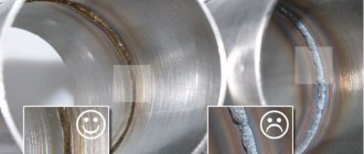
Cold welding is used to correct defects in cast iron castings using an arc method using various electrodes: steel, copper, copper with an iron shell, copper-nickel, and special ones. Defective areas to be welded are cut with pneumatic chisels or drilled out. A properly cut sink for tea leaves should have a bowl-shaped shape with sloping walls at an angle of 35–40° and an open bottom. Cracks should be cut down to their full depth. Compared to steel, the weldability of cast iron is worse. Significant fragility and increased sensitivity to cooling rate complicate the process of welding cast iron. Due to uneven heating during welding, the welded area has a non-uniform structure. Poor quality welding in a casting may result in the formation of cracks and other defects in the weld and base metal.
Welding with heated cast iron electrodes corrects defects located on the treated surfaces of cast iron castings (large shells, through holes and cracks). The castings are heated slowly. The heating temperature of the casting is determined using a contact thermocouple. After welding, the casting must be cooled slowly so that the welding site does not become chilled.
Gas welding with general heating of castings is used for gray cast iron castings that have a complex configuration and sharp transitions from the thin to the thick part. This welding method guarantees high strength and density of the welded joint, as well as uniformity of the chemical composition and mechanical properties of the base and deposited cast iron. The casting is heated before welding to 700 °C to prevent the appearance of cracks, stresses and the formation of chill in the casting metal.
Cast iron electrodes with a diameter of 5–6 mm are used as filler material. The filler material and welding sites are heated with a gas burner flame. After welding the castings, they are annealed at 450–500 °C to relieve stress.
Decorative correction of cast iron castings with putties is used to improve their appearance in places that are not subject to cutting. To prepare putties, epoxy resins of the ED-5 and ED-6 brands are used. After filling the defective area with putty and its hardening, the putty is cleaned off.
To increase the tightness, cast iron castings are impregnated with a solution of ammonia, ferric chloride with red lead and sodium nitrate and bakelite varnish under a pressure of 1–3 MPa. The most common impregnation is with bakelite varnish, which, after heating to 200 ° C and slow cooling, becomes impervious to water, gasoline and oil. After impregnation, the castings are dried in air for 2–3 hours.
Burnt
Another type of defect is burnout. Features. The surface of the casting can be covered with slagged, melted molding earth (chemical burn-in) and unslagged facing earth with metal penetrating into its pores (mechanical burn-in).
Reasons for education. The low fire resistance of the molding mixture creates conditions for its chemical burning to the casting with the formation of low-melting compounds with oxides of iron, manganese, etc. Low-melting compounds penetrate deep into the molding soil due to capillarity. Such a burn is only difficult to remove with pneumatic chisels and emery stones.
The main causes of mechanical burns are the high porosity of the facing earth, as a result of which liquid metal penetrates into the ground, the high temperature of the metal when pouring the mold and the metal pressure (pressure) when pouring high castings.