Marking and types of trays for heating mains
The main document regulating the dimensions of tray structures is Series 3.006.1-2.87; it also describes their marking, consisting of the following sequence of alphabetic and numeric symbols:
- L - tray, the plate that covers it is also designated similarly (letter P);
- d - placed behind the first digit indicates additional products;
- numbers from 1 to 38 indicate the serial number of the standard size and design of the product;
- The number behind the hyphen indicates the vertical pressure evenly distributed over an area of 1 square meter (m2) in kilogram-force (kgf), but more often in ton-force (tf), which the product can withstand;
- a - the letter after the second digit indicates brands with steel tabs.
There is another Series 3.006.1-8 of working drawings and standard sizes of tray elements with holes, which has a different symbol. In it, the alphabetic symbols and numbers according to their positions mean the following:
- KL - tray, PTU - overlapping corner plate, PDU - corner bottom plate, PTO - plate with a hole, LKO - tray product with a hole;
- the next three digits indicate the length, width and height of the product in centimeters;
- the last number after the hyphen is the design load in tf/m2.
Design and dimensional parameters of the tray LK 300.180.120-6 from Series 3.006.1-8
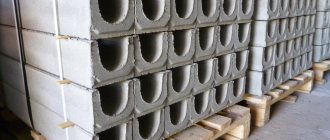
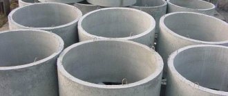
Underground structures are assembled from tray elements, which are divided into two groups:
- channels - products with a net height of less than 150 cm;
- tunnels - engineering communications from trays with a height of 180 cm or more.
The marking of channels and tunnels has an alphanumeric designation, similar to trays, and consists of the following symbols:
- KL - tray channels covered with slabs;
- KLP - channels of trays that rest on slabs;
- KLS - Structures made of two reinforced concrete products resting on the ends of each other’s side walls.
The number after the letter designation indicates the width of the channel in centimeters, the next number indicates the height of the tray in centimeters. The digital symbol after the hyphen is the workload in tf/m2.
Characteristics of trays of extreme standard sizes according to Series 3.006.1-2.87
What are drainage trays made of?
Various types of fiber-reinforced concrete are used to produce concrete trays. Crushed polypropylene fibers are introduced into the finished solution, which reduces the shrinkage deformation of products, as well as increases their resistance to bending forces. Metal fiber can also be introduced into the concrete composition.
Reinforced concrete drainage trays are also common, which are produced using cement grades no lower than M 500 and additional reinforcement.
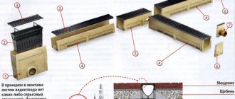
All channels, including those with a vertical weir, are equipped with gratings. This is necessary to protect them from leaves and other debris. The choice of material for the gratings used depends on the location of the main line and the expected load. The gratings are attached to the concrete using special screws. They can be removed for cleaning.
III. GUIDELINES FOR LABOR ORGANIZATION
Excavation work to excavate pits for sockets and trenches for tray blocks must be completed before installation work.
The blocks must be delivered to the work site in advance. At the exit bell pit, the outlet bell blocks and several tray blocks are unloaded (depending on the size of the boom of the truck crane). The remaining tray blocks are unloaded along the trench near the truck crane parking areas, and the upper bell blocks are unloaded at the pit of the upper bell. The blocks must be folded so that they do not interfere with the passage of the truck crane.
Crushed stone for crushed stone preparation is unloaded at both sockets and intermediate stops.
Excavation work to construct a trench for the tray is carried out by a team of workers consisting of: an excavator operator of 6 grades, and excavators: 3 grades. — 1, 2 sizes - 2.
Excavators carry out work on the rough leveling of the trench and pits after the work of the excavator, digging trenches under thrust spurs and under stops, and then finally planning the bottom of the trench under the lath, giving a slope.
The installation of the blocks is carried out by a team consisting of: truck crane operator 5 r. and erectors of structures: 4 grades. — 1, 3 sizes - 2.
In the process of performing work, the installer of 4-grade structures. gives instructions to the truck crane operator to lift and lower the blocks, monitors their correct installation.
Installers of structures 3 grades. they sling the blocks and direct them to the laying site, and also arrange crushed stone preparation.
To excavate trenches and pits, fill the cavities with soil with compaction and final leveling of the surface near the tray, the following are involved: an excavator operator of 6 grades, a compressor operator of 4 grades. and digger 3 sizes.
Types of drainage trays
According to the manufacturing method, concrete trays are divided into 2 groups:
- made by vibration casting. The material is compacted by vibration of the work table and the casting mold;
- made by vibration pressing. The material is compacted using a press. Such gutters do not have air bubbles inside, so the occurrence of cracks in their structure is unlikely.
According to their structure, channels are divided into the following types:
- ordinary;
- channels with a vertical spillway.
Concrete channels can be equipped with various types of gratings:
- cast iron gratings (their surface can be galvanized);
- steel gratings. Stainless steel can be used for their manufacture. Also, the surface of the grating can be galvanized;
- plastic grilles (made of very durable types of plastic).
Cast iron grating for a drainage tray of reinforced concrete products.
In addition, the gratings can be cellular or slotted. For example, a concrete drainage tray with a slotted cast iron grate can be used in areas with the highest weight loads.
Depending on the location and tasks, concrete gutters can be used for the following purposes:
- for drainage;
- for laying cables;
- for the construction of heating mains.
Trays can also have an internal slope for water drainage or be without a slope.
Dimensions
Trays are made in rectangular and trapezoidal shapes with a slope of internal walls. Their main dimensions:
- The standard length is 5970 mm; small concrete products of initial numbers have this standard size (at the discretion of the manufacturer, their length can be 2970 mm). Heavier, large-sized products starting with numbers L25 (weight more than 5 tons) are produced in sizes of 2970 mm for ease of transportation and installation;
- for all additional products with index d, the standard length is 720 mm;
- the width of the trays ranges from 420 mm to 4000 mm with the following gradation: 420 mm (L1); 570 mm (L2); 780 mm (L3 - L5); 1160 mm (L6 - L9); 1480 mm (L10 - L13); 1840 mm (L14 - L18); 2160 mm (L19 - L22); 2460 mm (L23 - L26); 2780 (L27 - L30); 3380 (L31 - L34); 4000 (L35 - L38);
- the height of the walls increases with increasing serial number and ranges from 360 mm for L1, L2 to 1700 mm for L38.
- wall thickness from 40 mm (L1) to 100 mm (L38);
- internal channel width - from 300 mm to 3600 mm;
- height of the tray from the inside from 300 mm to 1500 mm;
- bottom thickness - from 60 mm to 200 mm.
- the mass of the trays varies from 0.9 t for L1 with a concrete volume of 0.34 m3 to 9.38 t with a material volume of 3.75 m3 for L38.
- slabs of type KL and KLp are produced with a length of 2990 mm; for reinforced concrete products with an internal width of 300 and 450 mm, the length of the slabs is 740 mm.
- for additional prefabricated concrete products of 720 mm, the length of the overlapping slabs is 740 mm.
Installation diagram of reinforced concrete channels
Standard sizes
All manufacturers of reinforced concrete trays adhere to the same standards. In addition to length (L), width (B) and height (H), products are classified by hydraulic section (DN). These parameters determine the water throughput capacity of the drainage system.
To determine the required dimensions, a hydraulic calculation is performed using a special formula. It is better to entrust this work to a professional, as several factors must be taken into account. Large manufacturers offer customers free estimates of drainage systems with an area of 1000 square meters or more. m.
The weight and weight of the trays depend not only on the dimensions, but also on the load class, so they are taken into account only when calculating the costs of transportation and installation:
- D.N. The hydraulic section of the tray is the width of the internal section, denoted by the Latin letters DN. The numbers indicated after these letters correspond to the hydraulic cross-section of the product, expressed in millimeters. For example, DN100 - the width of the internal gutter is 100 mm. Manufacturers of drainage systems produce trays with sizes DN100, 150, 200, 300, 400, 500.
- L. Most often you can find trays with a length of 1000 (or 1050) mm on sale. Other possible sizes: 500, 1100, 1200, 2060, 2360, 2400, 2950 mm.
- B. The outer width of reinforced concrete trays for drainage is from 140 to 603 mm. This size depends not only on the hydraulic section, but also on the thickness of the walls of the product - it can be different.
- H. The height of the trays ranges from 60 to 700 mm. The documents may also indicate the hydraulic height, i.e. the internal height of the gutter. It also depends on the thickness of the walls of the product. Trays of small height are called shallow-sitting.
Material of manufacture
Trays are produced in accordance with GOST 13015.1-2003; the regulatory act Series 3.006.1-2.87 provides working drawings and identifies the following building materials from which tray reinforced concrete products are produced:
- the main component of their production is concrete of compressive strength class B15, B25, B30, B35, which corresponds to the strength grades of concrete M200, M300, M400, M450;
- for reinforcement, class AI, AIII reinforcement (GOST 5781-82), BpI wire (GOST 6727-80) is used;
- when constructing the fillings, VSt3kp2 steel is used (according to GOST 380-71 this is structural carbon steel, B - supplied according to standardized chemical properties and physical parameters, kp - boiling, sp - calm, ps - semi-quiet);
- anchor elements are made from class AIII steel (according to GOST 5781-82);
- For the production of mounting loops, class AI steel of grade VSt3sp2 or VSt3ps2 is used. The use of the latter in temperature conditions below -40 °C is unacceptable.
The trays are reinforced with frame and welded mesh elements in accordance with the drawings and reinforcement fixation diagrams from Series 3.006.1-2.87, while the thickness of the protective concrete layer is taken equal to:
- for walls of a monolithic structure less than 10 cm - 1.5 cm;
- for walls of products more than 10 cm - 2 cm with a permissible deviation of +5 mm.
Reinforced concrete channel and tunnel elements according to Series 3.006.1-2.87 - parameters
Purpose
Reinforced concrete trays (RCTs) for heating mains, due to a wide range of standard sizes, are used not only for their intended purpose, but also for other purposes, both in households and in the construction, municipal, and industrial sectors.
Reinforced concrete trays for heating mains play the following role:
- They protect water, gas, steam pipelines or cables from the physical pressure of the soil placed above them.
- They provide additional thermal protection for the pipeline, while saving money on heating water, steam or other coolant.
- Since the underground tray is covered with a protective cover on top and coated with waterproofing on the outside, moisture does not penetrate into it - in this way, internal utility lines are protected from corrosion.
- Also, the reinforced concrete tray for the heating main does not allow the pipeline to come into contact with the soil, various biological organisms and animals. This increases the corrosion resistance of the pipeline and significantly increases its service life.
- A concrete tray for the heating main protects the pipeline from the physical impact of the soil during subsidence, displacement as a result of earthquakes or erosion by groundwater.
- One of the popular uses of trays is to install them to drain various liquids. They can be used in the livestock farming industry on livestock farms for transporting liquid manure and organizing water supply channels. In land reclamation, trays are used for draining swampy areas. When running a household farm, using trays, you can supply water to the site from open sources, wells, pumps, and create channels for draining water from the territory.
Reinforcement schemes
Procedure for drainage from dividing strips
The drainage of surface water from highway strips, testing sites and embankments exposed to groundwater is characterized by a list of individual characteristics. Most often, they are caused by strictly individual contours of runoff directions in the plan, the presence of looped runoff areas and ramps with large-scale multidirectional slopes, proximity and interaction with the city territory, etc.
drainage of water from trays
The branches of transport arteries require the most efficient drainage of water and its redirection beyond the road surface. Drainage systems must provide a stable, unimpeded flow of liquid, directing it along a longitudinal slope in the required direction. If the exit ramps of highway interchanges cross embankments, then special throughput pipes are used for drainage.
Trays for water drainage from reinforced concrete
Reinforced concrete drainage (drainage, drainage) trays are made by vibrocompression or vibrocasting. Heavy, high-grade concrete is used. Class A steel reinforcement is placed inside, giving the product strength and high load-bearing capacity.
A vibro-compressed gutter differs from a vibro-cast gutter in that it has better characteristics and will last longer. The ends of the products are made for a locking connection, which prevents displacement of the elements of the drainage system during installation and operation. A hole may be provided in the bottom of the tray for vertical drainage into the sewer.
Varieties
According to the installation method, reinforced concrete drainage trays are distinguished:
- Edge. They are placed along the edge of roads at the same level or in a cascade (depending on the magnitude of the surface slope).
- Telescopic. Gutters of this type are used to drain runoff along a slope (from bridges, embankments, etc.). The elements of the telescopic drainage system are installed one inside the other.
Classification of gutters by cross-sectional shape:
- U-shaped - have the largest cross-sectional area, designed to drain large volumes of wastewater.
- U-shaped - designed to drain a small amount of wastewater, suitable for private suburban areas.
- Trapezoidal - for installation of a telescopic drainage system. The product has the shape of a trapezoid not only in cross section - one of its ends is wider than the second, and the narrow one is inserted into the next element.
Advantage of concrete products
Drainage gutters are made not only from reinforced concrete, but also from plastic, polymer-sand mixture, simple and polymer concrete.
Advantages of reinforced concrete trays:
- resistance to high loads;
- wide scope of application;
- low price.
Installation and waterproofing of tray structures
Installation of channels and tunnels is carried out in accordance with SNiP III-16-80 (Rules of work for the installation of prefabricated concrete and reinforced concrete structures) and SNiP III-4-80.
The basic rules for carrying out work include the following points:
- Installation begins after installing the cushion and checking the slopes and dimensions of the channel with a construction tool.
- When installed, the trays are hooked onto hinges or use grips in the form of strong metal rods inserted into the opposite walls of reinforced concrete products.
- When laying slabs, it is recommended to use pincer friction grips without the use of loops. Depending on the manufacturing technology of the plates, special holes in the products can be used for their installation; in the absence of loops and holes, sling loops are used.
- When laying elements, the seams are filled with grade 50 cement mortar; in places of deformation, the seam openings are filled with bitumen.
- If the installation is carried out using the semi-underground method, the seams between the floors are filled with bitumen mastic with a special filler in accordance with SNiP III-20-74, which regulates roofing, waterproofing and vapor barrier work.
- All metal connections must be coated with an anti-corrosion compound, and the tunnels must be concreted according to the appropriate unit.
- After installation, the sling holes are covered with grade 50 cement.
- It is allowed to install tray communications without upper and lower ceilings outside buildings with walls no more than 60 cm high, and in workshop channels with a depth of up to 50 cm.
- It is allowed to stretch communications in open channel passages with no load during possible shedding of the earth or the absence of fastening the walls with temporary supports.
- In closed tunnels, communications are pulled through installation openings.
- Backfilling of laid communications is carried out in evenly distributed layers with a thickness of 20 - 30 mm on both sides according to the excavation technology in accordance with SNiP III-8-76.
- Installation of reinforced concrete products with filling elements is carried out according to pre-marked markings.
Laying trays using special equipment
Waterproofing
When constructing tray engineering structures in areas with high groundwater levels, the following methods are used to protect tunnel and channel structures from moisture:
- Drainage is arranged, if its implementation is technically impossible, hydraulic insulation is carried out. In this case, the surface water level is considered to be 1 m below the ground level when deepening up to 4.5 m and 1 m below the top of the concrete concrete when deepening more than 4.5 m.
- Hydraulic insulation on the floors from the penetration of groundwater is carried out in accordance with SN 901-65; the prepared base for the coating must have a slope of 4%.
- When laying, the following types of hydraulic insulation are used:
- cold from asphalt;
- hot from asphalt;
- lining made of bitumen;
- composite materials from acids, petrolatum, bitumen mastic.
- The external surfaces of products outside the groundwater zone are coated with bitumen waterproofing. When laying heating networks for protection from surface water, one is guided by the relevant SNiP II-36-73.
- To increase the durability of reinforced concrete structures, reduce the labor intensity and cost of work, it is recommended to use waterproofing at a groundwater level of up to 20 m.
- The work is regulated by the instructions of SN 301-65 (clause 2.1) and the requirements of SNiP 2.03.11-85 regarding the protection of building structures from corrosion under aggressive influence of the aquatic environment.
- The waterproofing anti-pressure coating must be located at a height of no less than 0.5 m above the maximum groundwater level.
- Prefabricated tray elements of channels and tunnels must be placed on a pad of grade 100 concrete with a thickness of at least 10 cm, and the edges of the preparation must be reinforced with mesh.
- If the preparation is carried out in an aggressive water environment, it is carried out from high-density concrete of a group not lower than B6 in terms of water permeability.
- Another technology for creating a preparatory cushion in a trench is to tamp crushed stone into the soil and then pour it with bitumen until it is completely absorbed.
- Waterproofing units, expansion joints, protective barriers, parts for passing pipes and cables through the waterproofing layer must be made in accordance with SN 301-65
Cost of trays
Heating main trays, widely used in industry, construction, public utilities and agriculture, are produced for organizing open and closed channels, tunnels underground and on its surface. A significant number of standard sizes, availability, ease of installation, low price, significantly expand the scope of their application up to domestic use.
VII. MATERIAL AND TECHNICAL RESOURCES
A. Basic materials
| Name | Unit | Quantity |
| Tray blocks measuring 0.8×0.55×4 m | PC. | 20 |
| Output head (absorber) blocks | PC. | 4 |
| Blocks for entrance head | PC. | 4 |
| Entry head floor slabs | set | 4 |
| Storm gratings for the entrance head | set | 4 |
| Tow | kg | 12 |
| Cement mortar | m3 | 0,6 |
| Crushed stone | m3 | 4 |
B. Machinery, equipment and fixtures
| Name | Brand, GOST | Quantity |
| Truck crane | K-64 | 1 |
| Excavator | E-4010 | 1 |
| Shovels | GOST 3620-63 | 4 |
| Steel crowbars type LO | GOST 1405-65 | 3 |
| Roulette type RS-20 | GOST 7502-69 | 1 |
| Shurovki | TsNIIS Ministry of Transport | 2 |
| Caulks | GOST 11618-65 | 2 |
| Templates for checking slope slopes | — | 2 |
| Hemp cord | — | 40 m |
| Four-line grip | — | 1 |
| Cables 3 m long | — | 2 |
| Tamping | — | 1 |
| Steel sheet (striker) | — | 1 |
| Compressor | ZIF-55 | 1 |
Types of concrete trays
Concrete trays are made by pressing the original material, which gives additional strength to the product. In some cases, metal particles are added to the concrete to provide additional strength. Reinforced concrete drainage trays have a higher cost than products made from conventional concrete. Therefore, they are used exclusively in cases where increased strength is required.
Device and main characteristics
Galvanized steel rails are a cheaper option than aluminum, and they also provide some protection against oxidation due to the zinc on its surface. However, its disadvantage is the fact that this protection must be reinforced from time to time, representing somewhat less effectiveness.
Stage-by-stage installation of rails
The initial process of installing gutters is to measure the structures and determine the direction of water flow. To do this, simply observe the roof of your roof and measure, using the appropriate tools, all the compliments of the roof limits where the gutters will later be installed. Then you need to determine the location of the nozzle, that is, where the pipe will be installed that will drain the water from the roof to the ground. The most recommended locations to install nozzles are areas where there is no foot traffic and near drains or other flow systems. Once determined, trim will need to be cut to the gutter and this trim is usually done at two millimeters per metre. Soon the process of marking the supports that will have the function of supporting the gutter begins. The brackets vary depending on the type of path, but the recommended distance between them is from 50 centimeters to 1 meter. Please remember that this is a recommendation, not a rule, and there may be differences between the measures shown here and those determined by the responsible professional. Then install the supports that will receive the gutter
It is important that special fastening materials are used, such as bolts, wall-type bushings and supports that are strong enough to withstand the flow of water. Holes should be made on the wall using a drill to install the grommets, and then the brackets will be fixed with screws
Amendments must then be made when necessary. In some types of gutters splicing may not be necessary, but if present it is important to do it correctly. Therefore, according to the cutting direction, overlap the pieces so that the flow of water does not directly hit the seam, because over time, contact with water may break the connection and damage the gutter. Next, install your gutters and accessories. When properly prepared, simply install the gutter in the appropriate location, holding it in the most comfortable manner, depending on the type of gutter. Also install the material accessories so that the entire system is ready to go at the end of this step. And finally, the end of the service. The constant flow of water can damage the structure, and this is natural. To minimize the impact, you can use gutter protection products depending on the type of gutter. Contact your supplier and ask about the appropriate measures for your gutter type.
Frequently asked questions about gutters
Troughs are structures installed at the edge of the roof to direct the flow of rainwater to a more convenient location, bringing a number of benefits and conveniences to the consumer.
Concrete storm drainage trays can be classified according to the class of load they can withstand:
- Class C250 is used on roads where traffic intensity is characterized as low or medium, as well as in the area of small parking lots intended for parking passenger vehicles.
- Class D400 is used on high-traffic roads, in areas where gas stations are located, where there are clusters of garages and in small industrial areas.
- Class E600 is intended for drainage from highways, large industrial enterprises and railways.
- Class F900 has the greatest strength and is used for drainage from airports, ports and large logistics centers.
In domestic construction, polymer concrete drainage trays are used (they are cheaper than concrete ones) or concrete class C250.
All concrete trays can be divided according to their parameters. Currently, trays are produced in a standard length of 1 m and various internal sections, which can vary from 100 mm to 500 mm.
Classification and main dimensions
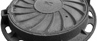
4.1 Types, main parameters and dimensions of hatches, their installation location are given in Table 1. The type of hatch should be selected depending on the installation location.
Table 1
| Type | Name | Rated load, kN | Full opening D, mm, not less | Depth of installation of the cover in the housing h, mm, not less | Reference weight, kg (gray cast iron) | Reference weight, kg (high-strength cast iron) | Recommended installation location |
| LM*(A15) | Lightweight, compact hatch | 15 | 450 | 20 | 40 | 30 | Green area, pedestrian area |
| L(A15) | Light hatch | 15 | 550 | 20 | 45 | 30 | |
| LU(A30) | Lightweight reinforced hatch | 30 | 550 | 20 | 50 | 30 | |
| C(B125) | Middle hatch | 125 | 550 | 25 | 70 | 45 | Parking lots, sidewalks and roadways of city parks |
| T(S250) | Heavy hatch | 250 | 600 | 35 | 105 | 55 | City roads |
| TM(D400) | Heavy main hatch | 400 | 600 | 50 | 130 | 65 | Main roads, gas stations |
| ST(E600) | Super heavy hatch | 600 | 600 | 60 | 170 | 80 | Roads with heavy traffic (airfields, docks, warehouse terminals and other objects with high loads on the road surface |
| STU(F900) | Extra heavy reinforced hatch | 900 | 600 | 60 | — | 100 | High load areas (airfields, objects with extremely high loads on the road surface) |
| * For underground communications with a channel depth of up to 600 mm from the outer surface of the manhole cover. Note – The installation depth of the cover in the body is regulated for hatches without a locking device in order to prevent spontaneous opening of the cover when a vehicle hits the edge of the cover. For hatches with a locking device, it is allowed to reduce the minimum installation depth of the cover. | |||||||
4.1.1 According to their design, hatches are divided as follows:
1 – general purpose (see Appendix A, Figure A.1);
2 – with a locking locking device on them. The design of the locking device is agreed upon with the consumer (see Appendix A, Figure A.2);
3 – covers with a recess in the design for filling with concrete of a class not lower than B30 in accordance with GOST 26633, a hatch body with a combined version of cast iron with concrete of a grade not lower than B30, corresponding to GOST 26633 (see Appendix A, Figure A.3);
4 – with a device for lifting the cover using a standard lifting mechanism. The design of the device must be agreed with the consumer;
5 – with reinforced sealing of the body with anchor bolts or special bosses on the body. The design of anchors, bosses and their number (at least two) are agreed with the consumer (see Appendix A, Figure A.4);
6 – with a cover consisting of two or more parts (see Appendix A, Figure A.5);
7 – with a cover hinged to the body (see Appendix A, Figure A.6);
8 – with a square or rectangular shape of the cover and (or) hatch body;
9 – with a self-leveling (floating) body (see Appendix A, Figure A.7);
10 – with a single body for two or more covers (see Appendix B, Figure B.1).
4.2 Types, main parameters and dimensions of rainwater inlets, their installation location are given in Table 2. The type of grate should be selected depending on the installation location.
table 2
| Type | Name | Rated load, kN | Living cross-sectional area S, m2, not less | Installation depth of the grille in the housing h, mm, not less | Reference weight, kg (gray cast iron) | Reference weight, kg (high-strength cast iron) | Recommended installation location |
| D(A15) | Small storm water inlet | 15 | 0,05 | 20 | 51,5 | 30 | Pedestrian zone |
| DB1*(V125) | Large storm water inlet | 125 | 0,075 | 35 | 90 | 65 | Parking lots and roadsides of urban roads |
| DB2**(V125) | 125 | 0,15 | 35 | 90 | 65 | ||
| DM1(S250) | Main storm water inlet | 250 | 0,075 | 35 | 110 | 70 | City roads |
| DM2(S250) | 250 | 0,15 | 35 | 110 | 70 | ||
| DU1(D400) | Reinforced rainwater inlet | 400 | 0,075 | 50 | 130 | 80 | Main roads, gas stations |
| DU2(D400) | 400 | 0,15 | 50 | 150 | 100 | ||
| DS1(E600) | Extra heavy storm drain | 600 | 0,075 | 50 | 150 | 100 | High load areas (airfields, objects with extremely high loads on the road surface) |
| DS2(E600) | 600 | 0,15 | 50 | 150 | 100 | ||
| * DB1, DM1 – on roads with longitudinal slopes i0 ≤ 0.005. **DB2, DM2 – on roads with longitudinal slopes i0 >0.005. Note – The installation depth of the grille in the body is regulated for rainwater inlets without a locking device in order to prevent spontaneous opening of the grille when a vehicle hits the edge of the grille. For rainwater inlets with a locking device, the minimum installation depth of the grate may be reduced. | |||||||
4.2.1 Based on their design, rainwater inlets are divided as follows:
1 – with equal width of the supporting part of the body along the contour (see Appendix B, Figure B.1);
2 – the minimum width of the longitudinal supporting part of the body adjacent to the road curb (see Appendix B, Figure B.2);
3, 4, 5 – with a minimum width of the longitudinal supporting part of the body adjacent to the road curb, and one right (version 3) or left (version 4), or both (version 5) short sides;
6, 7 – the minimum width of the short supporting part of the body adjacent to the road curb, or both short sides (see Appendix B, Figure B.3);
8 – a single body for two or more grilles (see Appendix B, Figure B.4; Appendix B, Figure B.1);
9 – reinforced sealing of the body, for which the latter is equipped with anchor bolts or special bosses on the body. The design of anchors, bosses and their number (at least two) are agreed upon with the consumer;
10 – by a grille, hingedly attached to the body;
11 – the shape of the gutter, repeating the shape of the drainage tray, in places of increased drainage;
12 – with a self-leveling (floating) body;
13 – locking device. The design of the locking device is agreed upon with the consumer;
14 – rainwater inlet body with a combined version of cast iron and concrete grade no lower than B30, corresponding to GOST 26633;
15 – with installation in concrete, plastic and polymer concrete trays;
16 – additional lateral water intake (Appendix B, Figure B.5).
4.3 Carpets (see Appendix D, Figure D.1)
The types, main parameters, rated load of carpets and their installation location are given in Table 3. The type of carpet should be selected depending on the installation location.
Table 3
| Type | Name | Rated load, kN | Recommended installation location |
| KL(A30) | Light carpet | 30 | Green area, pedestrian area |
| KS(V125) | Medium carpet | 125 | Parking lots, sidewalks and roadways of city parks |
| KT(S250) | Heavy carpet | 250 | City roads with heavy traffic |
4.3.1 According to their design, carpets are divided as follows:
1 – with a rotating cover;
2 – a cover hinged to the body;
3 – self-leveling (floating) body;
4 – round shape of the cover and (or) body;
5 – square or rectangular shape of the cover and (or) body;
4.4 The symbol of a hatch or storm inlet must consist of a definition of its type, design options, overall dimensions of the opening in centimeters and the designation of this standard.
Additionally, the symbol for the hatch includes the marking of the utility networks for which the hatch is intended: B – water supply; PG – fire hydrant; K – domestic and industrial sewerage; KK – cable duct; TSOD – technical means of traffic support; D – rainwater drainage; TS – heating network; MG – main gas; GKS – city cable network; GTS – city telephone network, etc.
Carpets are marked only with the letter designation of the utility network: MG - main gas, PG - fire hydrant; B – water supply, etc.
Utility markings are located on the outside of the cover.
Examples of symbols:
a) a light hatch with a square lid and an opening size of 60x60 cm:
L(A15)-TS-8-60x60 GOST 3634–2019,
where L(A15) is a lightweight hatch with a rated load of 15 kN,
TS - for the heating network,
8 - with a square cover,
60x60 - size of the square opening in the housing (in centimeters);
b) a heavy hatch with a locking locking device, with a self-leveling (floating) body and an opening diameter of 60 cm:
T(S250)-K-2-9-60 GOST 3634–2019,
where T(C250) is a heavy hatch with a rated load of 250 kN,
K - for domestic and industrial sewerage,
2 - with a locking locking device on them. The design of the locking device is agreed upon with the consumer,
9 - with a self-leveling (floating) body,
60 — diameter of the opening in the body (in centimeters);
c) a large rainwater inlet with a minimum width of the longitudinal supporting part of the body adjacent to the road curb, with an opening size of 37x78 cm for roads with a longitudinal slope 0 > 0.005:
DB2(V125)-2-37x78 GOST 3634–2019,
where DB2(V125) is a large rainwater inlet with a rated load of 125 kN and a clear cross-sectional area of at least 0.15 m2,
2 - minimum width of the longitudinal supporting part of the body, adjacent to the curb,
37x78 - size of the rectangular opening in the housing (in centimeters);
d) a main storm drain with an equal width of the supporting part of the body along the contour adjacent to the road curb, with a self-leveling (floating) body and an opening diameter of 60 cm for roads with a longitudinal slope 0 ≤ 0.005:
DM1(S250)-1-12-60 GOST 3634–2019,
where DM1(S250) is a main storm drain with a rated load of 250 kN and a clear cross-sectional area of at least 0.075 m2,
1 - with equal width of the supporting part along the edge,
12 - with a self-leveling (floating) body,
60 is the diameter of the opening in the housing (in centimeters).
How to make a tray Step by step instructions.
If you decide to make a drainage tray with your own hands, then you should act in the context of the following diagram:
You should start by preparing the molds for pouring. Contrary to popular belief, they can be not only metal, but also polymer
It is extremely important to thoroughly treat the inner walls of the mold with machine oil. After lubricating the mold, it is necessary to secure the reinforcement in it; Parts of the reinforcement should be fastened not only relative to the shape, but also relative to each other
As a rule, this stage of work is carried out using gas or electric welding. The molds should be fixed before pouring begins; even slight movement of the selected containers is considered unacceptable and may not have the best effect on the quality of the finished product. After a week, you need to carefully remove the formed channel from the pipe; if necessary, you need to cover it with a layer of paint or any anti-corrosion compound that is not rough after drying. This will help improve the efficiency of the sewer system due to the smooth internal structure.
This video shows an artisanal manufacturing method.
Even with total adherence to the described technology, the service life of a tray made at home may differ significantly from the period of operation of a factory product, which in itself is logical. However, if you follow the described scheme, the tray you make will not be inferior to the one that was made in the factory in terms of efficiency during operation.
Let's see how to make a U-shaped block for water drainage
Roads for cars and auxiliary units on their territory seriously suffer from the destructive effects of precipitation and other atmospheric factors. Precipitation in the form of rain seriously changes the mode of operation of roads, so its effective and timely drainage plays a fundamental role.
The maximum harm to the stability of the structure is caused by the so-called. free water. The operation process is accompanied by significant fatigue of road surfaces, destruction of expansion joints, and the appearance of cracks. In order to delay this process as much as possible, drainage structures are used.