Homemade charger for AA batteries
Today, there are quite a lot of different battery-powered devices. And it’s even more annoying when, at the most inopportune moment, our device stops working, because the batteries are simply dead, and their charge is not enough for the normal functioning of the device.
Buying new batteries every time is quite expensive, but trying to make a homemade device for charging finger batteries with your own hands is quite worth it.
Many craftsmen note that it is preferable to charge such batteries (AA or AAA) using direct current, because this mode is most beneficial in terms of safety for the batteries themselves .
In general, the transferred charge power from the network is about 1.2-1.6 times the capacity of the battery itself. For example, a nickel-cadmium battery with a capacity of 1A/h will be charged with a current of 1.6A/h.
Moreover, the lower the given power, the better for the charging process.
- 1 Manufacturing process
- 2 Charging from USB port
- 3 Conclusion
Manufacturing process
In the modern world, there are quite a lot of household appliances equipped with a special timer that counts down a certain period, then signaling its end. When making your own device for charging AA batteries, you can also use this technology , which will notify you when the battery charging process is complete.
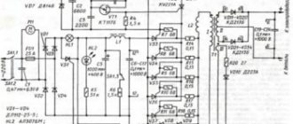
The charger for AA batteries is a device that generates direct current, charging up to 3 A/h. During production, the most common, even classic, scheme was used, which you see below. The basis, in this case, is the transistor VT1.
The voltage on this transistor is indicated by a red LED VD5, which acts as an indicator when the device is connected to the network. Resistor R1 sets a certain power of currents passing through this LED, as a result of which the voltage in it fluctuates.
The value of the collector current is formed by the resistance from R2 to R5, which are included in VT2 - the so-called “emitter circuit”. At the same time, by changing the resistance values, you can control the degree of charging. R2 is constantly connected to VT1, setting a constant current with a minimum value of 70 mA.
To increase the charging power, it is necessary to connect the remaining resistors, i.e. R3,R4 and R5.
Is it worth making such a charger?
This solution has its advantages:
- light weight;
- ease of manufacture;
- low cost;
- compactness.
But among the minuses, it is worth highlighting problems when charging from a generator and difficulties in operation at low temperatures. Also, the charger has low reliability and may not work at the most crucial moment. However, using it as a backup charger is a good option.
Now you know why you needed to study physics at school. Everyone can try to make a charger for lithium batteries with their own hands. This is not only saving money, but also new knowledge!
How to make a charger for AAA batteries with your own hands at home - Do it yourself
25.10.2019
Li-ion 18650 batteries are very widely used in many of the electronic devices we use today. For example, LED lights, laptop batteries, electric bicycles or Power Bank.
These batteries are a reliable source of power, so they are also very convenient to use in DIY projects. The shape of 18650 lithium-ion batteries resembles a AA battery, but the output voltage is 3.7 V with a capacity of 1600 to 3600 mAh (AA or AAA batteries have a voltage of 1.5 V/1.2 V).
However, at the moment, charging these batteries is still not an easy matter as commercial chargers are quite expensive. In addition, lithium-ion batteries require a good quality charger, otherwise the battery life will be degraded. A balanced charger works well, but it is available at a higher price range.
So in this tutorial we decided to make a Li-Ion charger that can charge four 18650s at the same time. This charger is very easy to make and does the job of a balanced charger by cutting off power to individual batteries once fully charged.
Step 1: Accessories
We will need several “spare parts” for our charger:
- general purpose printed circuit board
- module TP4056
- paper clips
- connector
- PCB switches
- 3.7V Li-Ion batteries
- Soldering iron
You can buy all this in different stores, especially in foreign ones, for example, Amazon or E-bay.
Step 2: Let's start collecting
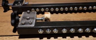
- Take a general purpose PCB and place the batteries on top of the board;
- Mark the distance between the edges of the batteries and their width on the circuit board;
- Unfold 8 paper clips and use pliers to cut clips from the edges as seen in the image above;
- A total of 8 U-clamps must be made (depending on the number of batteries being charged);
- Insert the U-shaped clamps into the circuit board so that the batteries can be installed between the clamps;
- The clips will act as battery holders;
- Also, use leftover pieces from the paperclips to make side supports;
- Attach the clamps well to the board as shown in the picture.
Note: Make sure the clamps are not connected to each other while soldering.
- Place the TP4056 charging module on the PCB as shown in the picture above;
- Using a marker, mark the module holes on the board;
- Solder a pin into each of the marked holes;
- Insert the module over the pins and solder carefully;
- Use the number of modules equal to the number of batteries being charged, i.e. one module per battery;
- Solder all modules onto the board as shown in the picture;
- Take the switches and solder them between each module on the PCB.
Note: Be sure to watch the video (below) and look at the images to avoid any mistakes.
- Refer to the wiring diagram above and solder all components together;
- Be sure to mark the polarity on the U-clip battery holders;
- Connect the terminals of the battery holder to the input terminals of the TP4056 charging module according to the polarity;
- Connect the modules so that they can transfer power from one stationary charger;
- Also, install connections between switches so that they can be used to independently control the power of the modules.
Step 5: Test the charger
- Insert the batteries into the battery holders on the board;
- Connect the mobile phone charger to one of the modules and turn on the power;
- An indicator will light on the module to indicate charging;
- Use switches to control the power supplied to the batteries;
- Turn off all switches if you only want to charge one battery;
- Turn on the switches according to the amount of battery charge at a certain time;
- Because each battery has a separate charger, so they will never face the problem of overcharging and recharging (the most common problem that damages lithium-ion cells).
Note: The TP4056 charging module is capable of providing 1A at 5V. Since we made the charger for 4 batteries, it is necessary to use a 2A mobile charger, such that at least 500mA is supplied to each cell.
So, friends, this concludes the lesson. Make it at home and use any number of lithium-ion cells without worrying about charging it.
Hello, dear readers of the site sesaga.ru. Lithium-ion (Li-Ion), nickel-cadmium (Ni-Cd) and nickel-metal hydride (Ni-Mh) batteries are widely used to power portable small-sized radio equipment. If the charging rules are followed, they last for several years and can withstand about 1000 charge-discharge cycles.
However, nickel-based batteries, such as Ni-Cd, require a special approach, as they have a “voltage depression” effect, which is also called the “memory effect”. The “memory effect” occurs during battery operation if it is systematically recharged without discharging
up to a voltage of 0.9 - 1 V [1].
Those. If you charge a battery that is not completely discharged, it will release energy only to the level from which charging began.
And since they are generally recharged this way, without going through full charge-discharge cycles, over time this level only increases, causing the battery capacity to decrease, which is why the user comes to the conclusion that the battery is beginning to deteriorate.
However, you should not be afraid of this electrochemical process, since it accumulates, is reversible and can be easily eliminated. To reduce the occurrence of the “memory effect,” manufacturers recommend periodically discharging batteries to a voltage of 0.9 - 1 V, and then charging them to 1.45 - 1.48 V.
The proposed simple universal charger allows you to partially automate this process and charge and discharge Ni-Cd and Ni-Mh batteries with a current of up to 260 mA.
Description of operation and device diagram
During operation, the charger constantly monitors the voltage on the battery being charged and automatically turns off the current when fully charged. It allows you to simultaneously and independently charge and discharge two AA or AAA batteries. The schematic diagram of the device is shown in the figure.
Functionally, it is designed as two channels with a common power supply, each having one charging
and
discharges
.
All switching for the charging and discharging processes is made by switches SA1
and
SA2
, and a cell phone charger with a stabilized output voltage of 5 V and a current of at least 1 A is used as a power source.
Let's consider the operation of one channel and start with the charging node [2]. While charging
The voltage on the battery being charged is monitored continuously.
On transistors VT1
and
VT2
a Schmitt trigger is assembled, which compares the voltage on the charging battery
GB1
or
GB2
with the reference voltage supplied to the
VT1
from the trimmer resistor
R2
.
The reference voltage is formed by the zener diode VD1
, resistors
R1
and
R2
.
Resistor R1
sets the operating current of the zener diode (about 10 mA), and resistor
R2
sets the desired threshold voltage.
When connecting a discharged battery to a charger, transistor VT2
closed, and
VT1
and
VT3
are open.
The collector current of transistor VT3
through the closed contact
SA2.1
of switch
SA2
charges the battery.
As soon as the voltage on the battery reaches a predetermined threshold value, the trigger and transistors VT1
,
VT3
will close, and
VT2
will open and turn on the
HL1
, signaling the end of charging.
Switch SA1
select the battery size and set the required charging current to 110 or 260 mA.
In the closed position of contact SA1.2
charging is carried out with a current of 110 mA, which allows you to charge batteries with a capacity of 850, 1100 and 1600 mA/h.
In the closed position of contact SA1.1,
charging is carried out with a current of 260 mA, which allows charging batteries with a capacity of 2100, 2600, 2700 and 2850 mA/h.
Switch SA2
charging
or
discharging
modes .
Push-button switch SB1
designed to force the charger to start if the battery is not completely discharged. Pressing the switch sets the trigger to the state corresponding to the charging mode.
Now let's look at the operation of the discharge unit
, which is powered by a discharged battery and when its voltage reaches 0.9 - 1.1 V, it automatically stops the discharge process [3].
When you briefly press the SB2
voltage from battery
GB1
or
GB2
to the base of transistor
VT5
through resistor
R11 .
If it exceeds the opening threshold of transistor VT5
(approximately 0.6 V), it opens and opens transistor
VT4
, through the collector-emitter section of which the battery discharges.
As the battery discharges, the voltage on it decreases, and when it drops below the opening threshold of the transistor VT5
, it closes and closes
VT4
.
The discharge process stops. HL3
incandescent lamp with a rated voltage of 1 V is used as a load and indicator of the operation of the discharge unit. Lamps with a voltage of 1.5 and 2 V can also be used.
Instead of a lamp, you can install a resistor with a resistance of 20 - 30 Ohms. In this case, there will be no indication and you will have to periodically check the voltage on the discharged battery.
Construction and details
The charge-discharge device is mounted on a printed circuit board made of single-sided foil fiberglass laminate measuring 60x45 mm and placed in a plastic case. Due to the simplicity of the circuit, the device can be assembled on a breadboard or even mounted.
The PCB is designed for two channels and its drawing is provided. Element labeling is shown for only one channel, since the second channel is identical.
The following figure shows the location of parts on the board, as well as their markings according to the circuit diagram.
Battery compartments, LED and incandescent lamps, as well as switches and push-button switches are located on the outer part of the housing. The battery compartments are first glued to the case with glue, and then additionally secured with screws. Screws are used with countersunk heads.
The installation of battery compartments and switches is carried out by hinged mounting directly inside the case. Push-button switches are located at the rear of the housing and are connected to the printed circuit board by a flexible wire.
The device uses resistors with a power of 0.125 W. Resistor R2 is a multi-turn trimmer of any type. Instead of transistors KT315B (VT1, VT2) and KT814B (VT3), you can use any with similar parameters. KT814 transistors are equipped with heat sinks.
We can replace the KT502 (VT4) transistor with any silicon one with a maximum collector current of at least 150 mA. The KT3102G (VT5) transistor was selected with an increased current coefficient and can be replaced with any one with similar parameters.
The device is connected to the power supply using a regular USB cable. The connector that is used to connect to the phone is cut off and the red and black wires are used to supply power. The red vein is a plus, and the black vein is a minus.
Setting up
If the device is assembled correctly and from serviceable parts, installation is reduced only to setting the reference voltage level
and, if required, setting
the charging currents
for finger and little finger batteries.
To set up the device, you must have a finger and little finger batteries. The finger type should be charged to a voltage of 1.48 - 1.49 V.
If there is no charger, then the battery is charged by this charger to a voltage of 1.48 - 1.49 V. During the charging process, the voltage on the battery is monitored by a measuring device. As soon as it is charged to the specified value, you can begin setting up.
Setting the reference voltage level
HL1 LEDs should light up
and
HL2
of both channels. A AA battery charged to a voltage of 1.48 - 1.49 V is inserted into the battery compartment and the reference voltage level of the first channel is adjusted.
Rotate the slider of trimming resistor R2
make the
HL1
. Then, by slowly rotating the engine in the opposite direction, the LED turns on. For accuracy of adjustment, this operation is repeated 2 - 3 times.
Now the battery is inserted into the compartment of the second channel and configured in the same way.
Setting the battery charging current
For ease of adjustment during installation, the terminals of the power transistor VT3
temporarily soldered to the board with pieces of mounting wire 70 - 80 mm long. The collector output wire is cut in half and a milliammeter with a measurement limit of at least 500 mA is connected to its ends.
Switch SA2
the first channel is switched to the “Charge” position, and
SA1
is switched to the “260” position and power is supplied to the device.
Next, take a discharged battery with a capacity of 2100 - 2850 mA/h, insert it into the appropriate box and monitor the charging current using a milliammeter. If the current is in the range of 250 - 270 mA, then do nothing. If the current is below the limit, the resistance of resistor R3
increase by several tens of ohms, if higher - decrease.
Then switch SA1
switch to position “110”, insert a discharged little finger battery with a capacity of 850 - 1100 mA/h into the corresponding box and adjust the charging current in the same way with resistor
R4
so that it is within 100 - 120 mA.
The second channel is configured in the same way. Now remove power from the charger and power transistor VT3
soldered into place as expected.
Setting the battery discharge current
All that remains is to check and, if necessary, adjust the discharge current
.
The device is not receiving power. The switch of the first channel SA2
is moved to the “Discharge” position, and the emitter circuit of transistor
VT4
is broken and a milliammeter with a measurement limit of at least 200 mA is connected to the gap.
The “Start” button starts the device and uses a milliammeter to control the battery discharge current, which should be within 80 - 100 mA. If the discharge current is higher, then a resistor with a resistance of 15 - 47 Ohms is connected in parallel with the lamp. The second channel is configured in the same way.
If you have any questions, be sure to watch this video.
That's all. Good luck!
Literature:
1. B. Stepanov, “Radio”, 2006, No. 5, p. 34, Let’s extend the “life” of Ni-Cd batteries! 2. V. Kosolapov, “Radio”, 1999, No. 2, p. 36, Simple charger.
3. A. S. Partin and L. Partina, “Radiomir”, 2007, No. 11, p. 13, Automatic “discharger”.
Add a link to a discussion of the article on the forum
RadioKot >Schemes >Power >Chargers >
| Article tags: | Add a tag |
Charger for four Ni-Cd or Ni-MH batteries of AA and AAA sizes.
Author: Pavlov Alexander Published 08/18/2010
2010
It all started with the need for four batteries for the camera, which means a charger was needed to quickly charge them and keep them in working condition. A Chinese “miracle” was purchased for good money in a reputable store under the name: Lenmar PRO290 Charger. Portable charger. Allows you to charge 2 - 4 AA and AAA batteries. Modern design and small sizes. When charging, it eliminates the “memory effect” from batteries. Shows the status of the battery charging process using an indicator. The best solution for charging AA batteries. Equipment: PRO290R (4 Ni-Mh AA batteries 2500 mAh)
The description of the kit was quite satisfactory, but the promises of the Chinese cannot be trusted. I opened it up and drew a diagram:
There are no protections or measurements there, especially not to mention a scheme for getting rid of the memory effect. There is a regular timer for 9 hours and two charge current control keys. I’ll describe the included batteries in a separate topic later. Having experienced disappointment, I put it all on the back burner, just in case, because it had already been purchased and would suddenly come in handy somewhere. I didn’t buy another, more expensive and sophisticated one, there are no guarantees that I will get what I want. It was decided to make our own memory design. Having scoured the Internet, I didn’t find anything that might be of interest. There were schemes that deserved attention, but as always, at least something was missing. By and large, what was needed was independent maintenance of batteries, and not as part of batteries. We had to do ours in a different case, using a microprocessor, with control of all the necessary parameters during charging and discharging, displaying the results on an LCD, or transmitting them to a computer, with independent charging/discharging of each of the four batteries. The case issue was resolved simply, I bought it for 130 rubles. another charger, threw out all the insides except the connection terminals, melted the unnecessary holes, and added the necessary ones. It turned out quite miniature, which means you can take it on the road, the issue of connecting to a computer has disappeared by itself (but maybe I’ll implement it over time). Appearance, what everything was assembled from:
(test output on the LCD, powered by the programmer) The diagram is shown below. The operating algorithm of the charger is designed as follows: When the power is turned on, the presence of batteries is checked by applying a charging current and measuring the voltage at the terminals; if it is in the range from 0.8V to 2.2V, then we assume that there is a battery. We check whether there was an emergency power outage; if there was, then load the previously saved parameters from the EEPROM memory (we save everything every 10 minutes during the charge cycle). If the shutdown is not detected, then we begin a new cycle, the modes of which are selected from the EEPROM memory, the same as the one selected earlier. It can be changed by pressing a button, after which the new parameters are saved in memory. Selecting one of 16 recorded modes allows you to charge and train a wide range of existing batteries. If you wish, you can adjust your individual settings in the EEPROM, there are no special problems. Pressing the button once does not change the mode, but turns on the battery discharge cycle before charging them. The discharge is carried out with a stable current of 0.36A and the discharge time is calculated to reach a battery voltage of 1V, thus obtaining the real capacity or simply training the battery to reduce the “memory effect”. Next, the charging mode is turned on, the end of which can occur when the specified voltage is reached, or when the battery temperature is exceeded, or after the specified charging time has elapsed. The end of the charge by changing the voltage dU has not yet been implemented, due to its difficult determination in old batteries and at a charge current significantly less than 1C. In fact, there are no obstacles here; if you really want to, you just need to change the program. At the end of the charging cycle, the batteries are “drip-charged” with short pulses lasting about 10 mS with an interval of 120 mS, with an average current of about 30 mA. The charger implements the principle of reverse charging to improve the charging characteristics of batteries; more detailed information can be found on the Internet. The ratio of charging and discharging pulses is 8%, i.e. 10mC discharge with a current of 0.36A, in a general charge cycle of 120mC, with a current of 0.39A, so the average charge current is also 0.36A. These current values were selected from many factors: ease of calculation, versatility when charging a wide range of batteries, reducing the heating of the device, but also not delaying the charging process; sometimes it is not possible to wait 10-14 hours. Tests in practice showed quite good results, but not immediately. It was necessary to refine the charge current stabilizers and reduce the supply voltage to 3.2V. This was the price to pay for being miniature. Even in the final version, during charging, the power dissipation on the stabilizers is slightly less than 3W. This leads to partial heating of the board and an increase in the temperature inside the case. Therefore, temperature control functions as a sensor for exceeding a specified limit, and not as an accurate measurement over the entire range. I can immediately imagine a lot of advice, use ready-made thermometers, such as DS18B20, but the issue is not the measurement, but the excess heat inside the case. The sensors were calibrated in the actual operating temperature range, from +35°C to +46°C; the batteries did not warm up higher, even in such hot weather this summer. There is also no point in taking temperatures less than +30°C into account. This is currently the only drawback of the device that irritates me a little, but I plan to eliminate it in the future. There was an idea to place the sensors on the outer surface of the batteries, but then you need to invent some kind of cover with wiring, which is not always convenient. There was an idea to combine the power supply and the microprocessor board, and the container with batteries separately, also not ideal, there are too many wires, and everything will have to be redone. In the meantime, it all works great and fulfills its intended purpose. A little about measuring internal resistance. The parameter is very interesting and useful specifically for analyzing the condition of the battery; there are many schemes and methods for determining it, but with the help of this charger you can only determine its approximate value. In a simplified version, two voltage measurements are taken, the first at the current charging current, and the second at the very end of the discharge current pulse, the difference in the voltage drop across the battery is divided by double the current, because there are two increments of dU at the charge current and at the discharge current: r=(Uз-Up)/(0.36*2). The results of measurements of the internal resistance of several new batteries were in the range from 0.03 Ohm to 0.05 Ohm, and testing of old ones (operation for more than 2 years) showed resistance values from 0.07 Ohm to 0.16 Ohm. Moreover, these readings continuously change, starting from their maximum value, then decrease to a minimum at the end of the charge cycle. Now about the power supply. It was planned to manufacture our own switching power supply for a voltage of 3.3V and a current of 2A, but a suitable design, size, parameters and price of 470 rubles were found on sale. Quite by accident, just because I had nothing to do, I copied a diagram from it and, if desired, you can repeat this design. This is what the purchased power supply looks like:
It is assembled according to this scheme:
I did not unwind the transformer, but its parameters are approximately as follows: Ferrite EE-16 (or EE-19), with a gap of 0.1 mm; The primary winding is about 95 turns of PEV-0.2 wire (inductance 1.3 mH); Secondary winding 4 turns with double wire PEV-0.51 (or MGTF-0.2); It is better to remove all unnecessary resistors in the adjustment circuits so as not to mistakenly switch to a higher voltage. Optimal power supply is from 2.8V to 3.3V. When the voltage is too high, the charge current stabilizers heat up more strongly, and when the voltage is too low, the opening threshold of the field-effect transistor may not be enough (real measurements showed Ugs=1.9B at Is=0.38A). In general, everyone decides for themselves what to do and what to buy. After some effort in assembling and writing a program, I got a fairly universal charger. This is what it looks like:
In the final version the scheme is as follows:
It consists of four identical charge and discharge current control units, with a circuit for measuring the temperature of each battery. The entire circuit is controlled by the PIC16F876A microprocessor. Displaying information on the indicator from a Nokia-3310 cell phone. To increase the accuracy of measurements, an external reference voltage driver +2.5V was used. The original version had charge current stabilizers on KT664A-9 bipolar transistors; as a result, it was necessary to provide sufficient base current; this required powering the device from +4V and an increased current from the microprocessor port. Naturally, the heating was significant, especially with the case closed, all the problems followed a chain. Therefore, I had to abandon bipolar transistors, use field-effect transistors with a p-channel, and switch everything to a reduced power supply (actually +3.1V in my circuit). Discharge current stabilizers on field-effect transistors with an n-channel type IRLML2502, but others with similar parameters can be used. The applied circuit solution ensures stable operation and maintaining stable currents, over a fairly wide range of operating voltages; moreover, this is just a charger, not a measuring device. Sometimes it is enough to evaluate the quality of the batteries being charged, what can be obtained from them after charging. Here's a small example. There are very old batteries, from a disassembled battery for a radio station (in the photo above, yellow without markings), they have been lying around in the trash since about 2001. and they themselves are even older. The battery parameters were as follows: voltage 12V, capacity 600mAh, Ni-Cd. There were 10 of them connected in series. Before charging, measuring the residual voltage showed that it was easier to throw them away, about 0.02:0.06V each. At the beginning, the charger did not recognize them at all (which is logical to the level of 0.8V), and with a “drip charge” it raised the voltage above 0.8V in 10 minutes. Then the reverse charge started, it didn’t last long at all, the voltage rose right up to 1.9V (the control was turned off, as it turned out, sometimes this is useful), and then gradually decreased to 1.55-1.65V. I didn’t mind the batteries, so I adjusted all the currents and voltages for them, and debugged the charging algorithm. At the end of all work, after 4 full charge-discharge cycles, the following parameters were obtained: pumped at a charge of 0.83 A/h (2.3 hours * 0.36 A), the maximum voltage was 1.49 V, measured capacity in the discharge cycle 0.43-0.45 A/h, internal resistance 0.12 Ohm. What can be considered quite tolerable indicators for throwaway batteries, they recovered to 70% of their capacity. If we also take into account that the discharge occurred with a current that was too high for them, 0.5 C, then these indicators are very encouraging. Now the “oldies” work in a wireless mouse, enough for several days of active use. But the Chinese Lenmar-2500mAh were generally disappointing. Instead of the promised 2.5 A/h, they barely reach 1.4 A/h, and the discharge current for them at 0.36 A (less than 0.2 C) can be considered the norm. All this after four full cycles of operation in the camera, and the charge is in the charger purchased in the kit. At the end of each charge cycle the batteries were quite hot. All this is about the information that can be obtained in the process of work. As you can see, special accuracy is not required for analysis. Next about the design. The LEDs are green so that they don’t hurt your eyes; the brightness is adjusted using resistors. A continuous glow indicates that the batteries are charging, and at the same time the symbol of each element shows this process. A flashing LED means the battery is charged and the cell symbol is completely dark while the trickle charging process continues. In the top line you can see how much time has passed since the start of the cycle of working with these batteries, but this time is not of particular value, for a general idea. Then, every 4 seconds, information about the batteries changes and the symbolic designation of the parameter is displayed behind a vertical line: Q=...A/h - capacity measured during discharge E=...A/h - capacity taken during charging R=....Ohm - internal battery resistance t=:°C - battery temperature Here are examples of output:
The battery number is continuously displayed on the indicator. If it is installed, then its symbol indicates charge/discharge/finished and the current voltage. If there are less than 4 batteries in the charger, or there is a bad contact, then “OFF” is displayed in the free position under the corresponding number. In the bottom line is a brief reminder about the operating mode of the charger, in particular: 2.5A/h batteries (charging time limit 8 hours 20 minutes) lack of voltage control (max 2.5V) maximum charging end temperature 45°C. The operating mode and parameters are changed with a single button. When pressed, we reset all variables, i.e. We start a new operating cycle, and on the LCD we see the established restrictions: battery capacity (for calculating the charge time), maximum voltage, maximum permissible temperature. In total, you can select one of 16 pre-recorded modes in the EEPROM memory. This set can be adjusted to suit your own needs and existing batteries. When programming, it is enough to make the appropriate changes to the EEPROM table. The structure of the record is as follows: in cell 00 the battery capacity (or rather, its charging time in tens of minutes) in cell 01 the maximum permissible temperature in cell 02 the maximum voltage of the charged battery in cell 03 00 (reserved for now) then in the same sequence for the second mode: in 04 cell battery capacity in cell 05 maximum permissible temperature in cell 06 maximum voltage of a charged battery in cell 07 00 So the entire table is filled out for sixteen modes, i.e. 16 times 4 cells, total 64 bytes. All numbers in hexadecimal format mean the following: Temperature in degrees, i.e. 45°C =.45 = 0x2D this is the number corresponding to the temperature. The maximum voltage is written on the basis that 1.45V = .145 = 0x91 Battery capacity in 1A/h = .20 = 0x14 (i.e. for a guaranteed charge (1/0.36) * 120% = 3.3 hours). This determines that the battery can be charged for the maximum possible time of 20*10=200 minutes or 3h.20m. and if during this time the charge is not turned off due to excess voltage or temperature, then it will stop at the specified time. By default, the following mode parameters are recorded for batteries: eight of them are 700mA/h, 1A/h, 1.3A/h, 1.5A/h, 1.8A/h, 2A/h, 2.5A/h, 2 .7A/h with a temperature limit of 43°C and a maximum end-of-charge voltage of 1.45V. the other eight are the same, but without maximum voltage control and a maximum temperature of 45°C. In the future, I plan to exclude modes that are not used at all (well, there are no such batteries, for example), but expand those that are used frequently. This can be done easily by changing the data in the EEPROM. The contents of cells starting from address 0x40 and beyond should not be touched. The currently saved parameters are recorded there. Paying attention!
The device should not be used to charge conventional AA or AAA batteries. If the charging mode is turned on without maximum voltage control, or it is set to more than 1.5V, then the device will try to charge such batteries, with all the negative consequences of this process. Now a little about the insides of the charger. There is no point in presenting your own version of the printed circuit board, due to the need for modifications (remove KT664 on each channel and in its place install IRF7306 paired with KT3107 or BC856, slightly adjust the printed conductors). For a general idea, the boards look like this:
The LEDs are not wired yet. On the outside of the case there is only a power connector and a mode selection button. Before final assembly, it doesn’t hurt to check the serviceability of the entire board and select some elements, if necessary. In my version, everything worked immediately and without configuration. To start the test program, hold the button pressed and apply power. Next, with the button you can switch three operating modes: 1 Charge on (checking and setting the charge current to 0.39A) 2 Discharge on (checking and setting the discharge current to 0.36A) 3 Temperature measurement (calibration of sensors and adjustment of the temperature range) V In the third test mode, the measured temperature from each sensor is displayed on the LCD; if there is a significant scatter, select resistors in the circuit of the corresponding diode. The range is adjusted by selecting R11 C14 (see diagram). There were attempts to simulate the circuit in Proteus, everything worked until a certain stage, until the program introduced the task of filtering ADC measurements using the simplest method of accumulating and averaging values. Problems immediately arose: all cycle periods, as well as LCD updates, were terribly stretched out, and the connection to real time was lost. During debugging on a live microprocessor, there are no such “brakes”, and the measurement readings are very stable. Therefore, everything was checked there at the level of individual nodes, which makes no sense to post. The existing charger has been tested and is already working, but the development of the program has not yet been finalized. Even during the writing of this text, several new ideas arose to improve the work and add new functions. If desired, programmers will be able to implement any operating algorithm themselves; here is only the basic principle of how to control the independent charge of four batteries. I ask experts not to judge strictly, I am an electronics engineer, not a programmer. I apologize if everything is described chaotically, I was in a hurry to finish it quickly before the start of the competition. There will be questions, I will try to answer.
Files:
MK firmware.
As usual, we put the questions here.
| What do you think of this article? | Did this device work for you? | |
| 66 | 1 | 0 |
| 1 | 1 |
Making a homemade charger for AA batteries
First, let's find out what a battery is. We open the relevant literature and read:
Ozhegov's Dictionary:
- Small rechargeable battery.
Ushakov's Dictionary:
- Small electric battery for flashlight.
Efremova's dictionary:
- A small battery device for increasing voltage or supplying energy.
Yes, it's a complete mess. Mrs. Efremova’s definition is especially touching. We won’t get help from the great and mighty “bisons”. And all because, from a technical point of view, the concept of “battery” does not exist.
Most of those who are far from electrical engineering use this diminutive word to call almost all autonomous current sources - from galvanic cells to batteries and batteries assembled from them. With one condition, that such a source fits into your pocket.
For example, no one would call a car battery a battery. This is a Battery with a capital B!
More advanced users use the word “battery” only to refer to galvanic cells and batteries assembled from them, but do not touch batteries and rechargeable batteries.
So what are all these devices actually called? The issue is resolved simply. It is enough to understand two definitions:
- A galvanic cell is a single device that generates electrical energy through internal irreversible chemical processes.
- A battery is a single device capable of storing electrical energy through internal chemical changes and subsequently releasing it through reverse chemical processes.
In other words, something disposable (worked and thrown away) is a galvanic cell. Something that can be charged repeatedly is a battery. If the elements are connected to each other according to one scheme or another, then this design is called a battery. For galvanic cells – a battery of galvanic cells. For batteries – a battery of batteries or a rechargeable battery.
Thus, in the topmost photo in the first and second positions from left to right there are batteries of galvanic cells. The first is assembled from 6 elements, the second (it is often called flat) - from three.
The third position shows a nickel-cadmium battery, the fourth and fifth positions show galvanic cells, and the last position shows a battery consisting of two nickel-metal hydride batteries.
But with a clear conscience we call all this “batteries”, and then we get offended when they can’t understand us! As for the car battery, which, oddly enough, is not called a “battery”, it is precisely a battery consisting of six batteries (popularly called “banks”).
Expert opinion
Alexey Bartosh
Specialist in repair and maintenance of electrical equipment and industrial electronics.
Ask a Question
Interesting. Many people believe that mobile devices contain batteries (note, not just any “batteries”). In fact, all smartphones, telephones and other similar equipment contain single batteries, not batteries. An exception may be a laptop battery, consisting of a set of single batteries.
On the left is a battery for a phone, on the right is a battery for a laptop, consisting of six batteries
Main characteristics of batteries
We've sorted out the terminology, now let's see what types of batteries there are and how they differ from each other.
Form factor
Modern batteries - both galvanic cells and batteries based on them - are available in various form factors. The most common are cylindrical and disk. Some batteries may be rectangular in shape.
The most popular sizes of galvanic cells and batteries
Charging galvanic cells is not only useless, but also dangerous.
If you force a battery to do something for which it is not intended, for example, forcefully “fill” voltage into it, then the cell may lose its seal and “leak,” flooding everything with electrolyte. But this is also a lesser evil.
It’s much worse when, when trying to charge, the battery overheats and explodes. Here it’s not far from an injury, and a stone’s throw from a fire. Thus, under no circumstances should you charge a completely discharged galvanic cell.
But it is not all that bad. Yes, a disposable battery cannot be restored, but it can be recharged without waiting for it to completely discharge. By recharging periodically, it is quite possible to extend the life of the galvanic cell by double or even triple.
Where does the extra energy come from in a battery whose chemical reactions are irreversible? The fact is that during the operation of the galvanic cell, the starting materials are not fully used.
Even a completely discharged battery still has a lot of untapped potential. If the battery is completely dead, it will not be possible to revive it.
But if the element is periodically “shake” with small charging currents, then it will use up the components more fully and will be able to last longer.
Important! Even recharging a galvanic cell may carry a certain danger of an explosion or fire. Therefore, if we nevertheless decide to do this, we must clearly understand that we are doing this at our own peril and risk.
How to distinguish a disposable battery from a rechargeable battery
We found out what the batteries that can be recharged are called. Their name is batteries. But how to distinguish a galvanic cell from a battery, especially if both are made in the same form factor? This is not difficult to do.
By voltage
No battery produces exactly 1.5 V. It can be 1.2, 1.6, 3.2, 3.7 V, but never 1.5 (see the “Output Voltage” section). If the cell body indicates a voltage of 1.5 V, then this is clearly not a battery. But this rule does not work for batteries. If a battery consists of several cells, then its output voltage can take on different values.
Thus, it is quite difficult to clearly distinguish a rechargeable battery from a battery of galvanic cells by voltage.
According to the accompanying inscriptions
Almost always, the manufacturer indicates its electrical capacity on the battery case. There are no such inscriptions on disposable batteries.
In addition, the type of battery is always indicated - the composition of the electrolyte and the material of the electrodes. In the photo below, we see a nickel-metal hydride battery on the left, and a lithium-ion battery on the right.
| [td] Sergey Chernov, Samara km450 (At) mail. ru |
Many diagrams of devices for charging nickel-cadmium pen-type (Ni-Cd) batteries have been published. But when the need arose to assemble a charger for myself, I couldn’t find anything to my taste.
You can, of course, buy a ready-made one, but this is not for a radio amateur. I had to develop my own. The proposed device is designed to charge AA batteries of all types, operates in automatic mode, is easy to repeat, is small in size and does not contain scarce parts. The appearance of the structure is shown in Fig. 1.
The device is available for repetition by beginning radio amateurs.
Rice. 1.
The device contains two identical battery charging channels, since it was designed specifically for its needs. One is designed to charge two AA batteries with a capacity of up to 2600 mAh, the other three AAA batteries with a capacity of up to 900 mAh. The schematic diagram is shown in Fig. 2.
The device is powered from a 220V network through a small-sized transformer T1 and a rectifier VD1, the output voltage of which at full load is about 9 volts.
Operation is indicated by two two-color LEDs, the red light of which signals the charging process, and the green light indicates its completion.
Rice. 2. Schematic diagram
The DA4 TL431 chip (analogue of LM431) contains a precision reference voltage source, and the DA1 and DA2 LM317T chips contain a charging current stabilizer, the value of which is determined by the battery capacity and is a tenth of it.
The control and indication circuit is assembled on a DA3 LM393, consisting of two open-collector comparators, keys for controlling charging current stabilizers on transistors VT1, VT2, an operation indicator on transistors VT3, VT4 and two-color LEDs VD6, VD7.
Description of work.
When connecting discharged batteries, the voltage at the direct inputs of the comparators is lower than the reference voltage at the invert ones. At the outputs of the comparators, accordingly, there is a zero potential, which leads to the opening of transistors VT1 and VT2.
Current stabilizers are turned on, the value of which is determined by resistors R29-R32. The resistor resistance value in ohms, according to the manufacturer's specifications, is calculated using the formula 1.25v/Ia. The board has space for two resistors for easy selection. I don’t have R32, it’s not useful.
Transistors VT3 and VT4 are closed, LEDs VD6, VD7 glow red.
At the end of charging, transistors VT1 and VT2 close, charging the batteries stops. Transistors VT3 and VT4 open, the LEDs glow green. Next, the batteries are under a small current of the order of 1 mA, which is almost completely safe for them but is necessary for the stable operation of the comparators, and they can remain in this state for a long time.
The comparators have a small hysteresis of the order of 10 mV, determined by resistors R16, R17, R19 and R20. Two resistors are included for ease of selection and reservation of space on the board when wiring it. One per comparator was practically enough. During the design, the PCAD 4.5 program was used.