Class “A” and “B” - are the differences significant?
For many car enthusiasts, spring stiffness by color is equivalent to stiffness by class.
Class “A”, regardless of color, is more stringent than class “B”. In fact, this is not an entirely true statement. Class “A” is really more suitable for cars that are often used under heavy load. But the difference here is quite small - about 25 kg. Despite the mandatory application of markings, there are still samples on which it is absent. In this case, even if the color coding of the elements is identical, it is better to refuse to purchase and use them. Many motorists underestimate the importance of high-quality springs, especially during intensive use of the car. It’s not for nothing that the springs are marked by color - this makes it much easier for a novice driver who is replacing this element with his own hands for the first time. Purchasing products of appropriate quality, albeit at a higher price, will inevitably pay off with a softer ride, less wear and tear on the car, and less stress on the driver himself. It has been scientifically proven that high vibration loads on a person lead to rapid fatigue and decreased concentration when moving.
Properties of suspension springs
When torsion bars on vehicles were replaced with springs, handling improved and suspensions became more convenient to maintain. Springs maintain the vehicle's ground clearance, reducing vibrations and shocks while the vehicle is moving.
To make the ride comfortable, you need to choose the right parts. If the technical characteristics are unsuitable, then the positive properties of the suspension will be reduced to zero
Therefore, it is important to consider the following parameters:
- diameter - its increase affects rigidity;
- number of turns - as the number increases, the rigidity decreases;
- form.
Often, car owners strive to install stiffer parts in the suspension. This helps to increase the sensitivity of the steering wheel to the driver's control, but the grip on the road deteriorates.
Fans of a sporty driving style believe that, on the contrary, it is better to install parts with reduced rigidity. However, this suspension can create problems on country roads.
Let's take a closer look at which springs are best installed on a VAZ.
Elastic force and Hooke's law
Types and types of springs
First, let's define the basic terms that will be used in this article. It is known that if you influence a body from the outside, it will either acquire acceleration or become deformed. Deformation is a change in the size or shape of a body under the influence of external forces. If the object is completely restored after the load is removed, then such deformation is considered elastic; if the body remains in an altered state (for example, bent, stretched, compressed, etc.), then the deformation is plastic.
Examples of plastic deformations are:
- clay crafting;
- bent aluminum spoon.
In turn, elastic deformations will be considered:
- elastic band (you can stretch it, after which it will return to its original state);
- spring (after compression it straightens again).
As a result of elastic deformation of a body (in particular, a spring), an elastic force arises in it, equal in magnitude to the applied force, but directed in the opposite direction. The elastic force for a spring will be proportional to its elongation. Mathematically it can be written this way:
F = - k x;
where F is the elastic force, x is the distance by which the length of the body has changed as a result of stretching, k is the stiffness coefficient necessary for us. The above formula is also a special case of Hooke's law for a thin tensile rod. In general form, this law is formulated as follows: “The deformation that occurs in an elastic body will be proportional to the force that is applied to this body.” It is valid only in cases when we are talking about small deformations (tension or compression is much less than the length of the original body).
Video
In this video you will learn how to determine spring stiffness.
Series connection of springs:
1/ktot = 1/k1 + 1/k2 +. + 1/kn
Or, if these are two springs connected in series, then you can use the following formula:
However, we should also remember Hooke's law: F = kl In a series connection there are n springs with stiffnesses k1, k2, and so on. From Hooke's law it follows that F = kl. The sum of the elongations of each spring is equal to the total elongation of the entire connection l (or x, it is written differently in textbooks)1 + l2+. + ln = lc. (by the way, this is one of the properties of a series connection) According to Hooke’s law, we can derive the following equation: l = F/k, l1 = F/k1, etc. Actually, further from this expression follows: 1/ktot = 1/ k + 1/k +. + 1/kn. Actually, from here we get: ktotal = 1/1/k + 1/k +. + 1/kn. Well, as you already understood, k will go up, and it will be inversely proportional to the numerator, which in turn depends on the stiffness coefficient.
When connecting two springs in parallel, having stiffness coefficients with
1,
c
2 (Fig. 2.5), the displacement of the body is equal to the deformation of each of the springs:
Read also: How to make lugs for a walk-behind tractor with your own hands
. (2.9)
R
is. 2.5 Parallel connection of springs
The elastic force of an equivalent spring with a stiffness coefficient c
* will be equal to the sum of the elastic forces of two installed springs, from where, taking into account (2.9), we obtain
,
. (2.10)
Formula for determining hardness
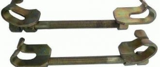
Shock absorber spring extractor drawing
The formula studied by modern schoolchildren on how to find the stiffness coefficient of a spring is the ratio of force and a quantity showing the change in the length of the spring depending on the magnitude of a given impact (or
elastic force equal in modulus to it). This formula looks like this: F = –kx. From this formula, the stiffness coefficient of an elastic element is equal to the ratio of the elastic force to the change in its length. In the international system of units of physical quantities SI, it is measured in newtons per meter (N/m).
Another way to write the formula: Young's coefficient
Tensile/compressive deformation in physics can also be described by a slightly modified Hooke's law. The formula includes the values of relative deformation (the ratio of the change in length to its initial value) and stress (the ratio of force to the cross-sectional area of the part). Relative strain and stress according to this formula are proportional, and the proportionality coefficient is the reciprocal of Young’s modulus.
Young's modulus is interesting because it is determined solely by the properties of the material, and does not depend in any way on the shape of the part or its dimensions.
For example, Young's modulus for one hundred
is approximately equal to one followed by eleven zeros (unit of measurement - N/sq. m).
The meaning of the concept of stiffness coefficient
Stiffness coefficient is a proportionality coefficient from Hooke's law. It is also rightfully called the elasticity coefficient.
In fact, it shows the amount of force that must be applied to an elastic element to change its length by one unit (in the measurement system used).
The value of this parameter depends on several factors that characterize the spring:
- The material used in its manufacture.
- Shapes and design features.
- Geometric sizes.
Based on this indicator, you can
Conclude how resistant the product is to loads, that is, what its resistance will be when an external influence is applied.
Features of calculating springs
Showing how to find the spring stiffness, the formula is probably one of the most used by modern designers. After all, these elastic parts are used almost everywhere, that is, it is necessary to calculate their behavior and select those that will ideally cope with their assigned responsibilities.
Hooke's law very simply shows the dependence of the deformation of an elastic part on the applied force; engineers use more accurate formulas for calculating the stiffness coefficient, taking into account all the features of the ongoing process.
- Modern engineering considers a cylindrical coil spring as a spiral of wire with a circular cross-section, and its deformation under the influence of forces existing in the system is represented by a set of elementary shifts.
- In case of bending deformation, the deflection of the rod located at its ends on supports is considered as deformation.
Determination of the stiffness coefficient
The stiffness coefficient (it is also called the coefficient of elasticity or proportionality) is most often written with the letter k, but sometimes you can find the designation D or c. Numerically, the stiffness will be equal to the magnitude of the force that stretches the spring per unit length (in the case of SI - 1 meter). The formula for finding the elasticity coefficient is derived from a special case of Hooke’s law:
Read also: Face mills for metal GOST
The greater the stiffness value, the greater will be the resistance of the body to its deformation. Hooke's coefficient also shows how resistant a body is to external loads. This parameter depends on geometric parameters (wire diameter, number of turns and winding diameter on the wire axis) and on the material from which it is made.
The SI unit of stiffness is N/m.
Series-parallel connection of power supplies
Transistor connection
Who’s stopping you from connecting batteries or batteries simultaneously in series and in parallel? But is that really possible? Can). Using an example with water towers, it might look like this:
Here we see two towers, each of which consists of two turrets, and these two large towers are connected by a pipe.
Very often, a series-parallel connection is used in electric vehicles. I recently made a battery for my electric bike from li-ion 18650 batteries. My electric bike required a voltage of 36 Volts. So, now let's turn on the logic. One battery produces 3.6 Volts. To get 36 Volts, I need to connect 10 batteries in series.
To make it easier to understand, I will draw them not according to GOST:
Hooray! I got 36 volts for my electric bike. But the problem is that one such battery can deliver a current of 2800 milliamps to the load for 1 hour or 2.8 amperes for 1 hour. This parameter is indicated on batteries as mAh. I wrote about this in detail in this article “How to measure current and voltage with a multimeter.”
The fact that I connected all the batteries in series does not mean that their capacity has increased 10 times. Only the voltage increased 10 times, since I connected them in series. That is, the total amount turned out to be 36 Volts and the same 2800 mAh as for one battery.
Therefore, in order to increase the capacity, I must connect exactly the same branch of batteries in parallel to this branch, otherwise my electric bike will not travel even a couple of kilometers. I want to ride all day!
No sooner said than done. We connect another branch of 36 Volts. You haven't forgotten the rule that when connected in parallel, the voltage should be the same? As a result, we get something like this:
In total, we received the same notorious 36 Volts, but the capacity has doubled. 2800 mAh +2800 mAh = 5600 mAh. Well, with such a battery you can drive a little further. But this also seemed not enough to me, so I added 2 more branches. As a result, my homemade battery for an electric bicycle should schematically look like this:
What does hardness depend on?
The spring stiffness depends on several parameters:
- spring geometry;
- type of material;
- coefficient;
- service life.
Spring geometry
The stiffness of the coil spring is affected by:
- number of turns;
- their diameter;
- The diameter of the wire.
The winding diameter is measured from the axis of the spring. Since the length of the wire in the spring is significantly greater than the length of the elastic rod, the resistance to external deformation increases many times over.
Wave springs consist of metal strips wound edgewise around a circle of a given diameter.
Their main geometric parameters:
- number of turns;
- number of waves per turn;
- tape section.
Material type
Each material has a conditional elastic limit, which characterizes its ability to recover from deformation. If this limit is exceeded, irreversible changes occur in the structure of the material.
Elastic limit is a mechanical characteristic of a material, showing the maximum stress at which only elastic, reversible deformations occur.
The elastic limit is measured in pascals and determined by the formula:
where F is the action of an external force on the sample under study, leading to damage, and S is its area.
In addition to the elastic limit, there are such elasticity characteristics of materials as elastic modulus (Young’s modulus) and shear modulus, stiffness coefficient and others. They are all interconnected, therefore, having found out the value of one of the quantities using a lookup table, you can calculate the others.
Coefficient
According to Hooke's law , at small deformations, the absolute magnitude of the elastic force is directly proportional to the magnitude of the deformation.
This linear relationship is described by the formula:
where k is the stiffness coefficient, and x is the amount by which the spring was compressed or stretched.
Deformation is considered small when the change in body size is significantly less than its original size.
Lifetime
Being under tension causes a gradual, irreversible deformation called spring weakening .
The stiffness of the spring affects its service life, as does the force of impact. Spring designers, having previously calculated these parameters, conduct tests on prototypes before starting mass production. In special installations for testing material fatigue, they are compressed and released a certain number of cycles, separately checking the behavior of the springs at maximum and minimum load.
Examples of problems for finding rigidity
Problem 1
A force F = 100 N acts on a spring 10 cm long. The length of the stretched spring is 14 cm. Find the stiffness coefficient.
- We calculate the absolute elongation length: x = 14-10 = 4 cm = 0.04 m.
- Using the formula, we find the stiffness coefficient: k = F/x = 100 / 0.04 = 2500 N/m.
Answer: The spring stiffness will be 2500 N/m.
Problem 2
A load weighing 10 kg, when suspended on a spring, stretched it by 4 cm. Calculate the length to which another load weighing 25 kg will stretch it.
- Let's find the force of gravity deforming the spring: F = mg = 10 · 9.8 = 98 N.
- Let's determine the elasticity coefficient: k = F/x = 98 / 0.04 = 2450 N/m.
- Let's calculate the force with which the second load acts: F = mg = 25 · 9.8 = 245 N.
- Using Hooke's law, we write the formula for absolute elongation: x = F/k.
- For the second case, we calculate the stretching length: x = 245 / 2450 = 0.1 m.
Answer: in the second case, the spring will stretch by 10 cm.
How can you measure hardness?
Measuring instruments
Devices for testing springs for compression-tension control the applied force using a strain gauge, as well as changes in their length, displaying the indicators on the display. Without a special device, you can measure axial stiffness using a dynamometer and a ruler.
There are also instruments for measuring the transverse stiffness of springs. To do this, you need to measure the displacement of several points of the spring, determining the distance and angle between them.
Practical problem
The easiest way to measure the stiffness of a spring is to conduct a standard school experiment with a tripod and weights suspended from a spring.
To measure the axial stiffness of a coil spring, use:
- a tripod on which the spring is attached;
- a hook that is attached to its free end;
- weights with a known mass, which are suspended on the free end of the spring;
- ruler to measure the length of the spring with and without a load.
By taking several measurements with weights of different masses and calculating the force of gravity acting on the spring in each of them, you can plot the dependence of the length of the spring on the applied force and find out the average value of the stiffness coefficient.
Determination of water hardness using instruments and “by eye”
It can be assumed that water contains a large amount of alkaline earth metal salts based on the following characteristics:
- Soap and washing powder do not foam well;
- limescale forms on the surface of heating devices;
- the water has a bitter taste and the tea takes longer to brew than usual;
- when boiling, a characteristic film forms on the surface of the water;
- Meat products are poorly cooked.
1. Water hardness strips.
Sold in Medtekhnika pharmacy stores, they show the measurement result with an accuracy of 1-2°F.
Instructions: lower the hardness strip into a glass of water, wait until the indicator with which it is soaked changes color, then compare it with the standard scale.
2. Express tests for aquariums.
This method is based on the titration method.
Example of an aquarium hardness test
Instructions: pour 5 ml of water into a test tube and add the reagent containing the indicator drop by drop. The number of drops of the reagent required for the solution to turn from yellow to blue is equal to the number of degrees of hardness, which ones are indicated in the instructions for the test.
3. Special devices.
The simplest and most accurate method for determining water hardness is titration. It is based on the reaction of indicators, their ability to change color when reaching a particular concentration in a strictly defined amount of water containing salts. In laboratories, titration results are processed using a photocolorimeter.
There are devices whose operating principle is to measure the electrical conductivity of water. The conductivity level is directly proportional to the concentration of calcium and magnesium salts dissolved in water. There are devices on sale such as a TDS meter (total dissolved solids, or “salt meter”) and an EC meter (conductivity meter).
Example of a TDS meter
The TDS meter gives the result in ppm. The device shows the total salt content and specific electrical conductivity of water. The EC meter additionally shows the specific resistance of the solution in µS/cm (micro Siemens). TDS result = k * EC, where k coefficient is in the range of 0.55–0.80 (average value 0.67).
TDS and EC meter in one device. More expensive, but more convenient
With the help of such devices it is convenient to monitor and maintain the required water quality in aquariums or for watering plants sensitive to increased hardness.
More about methods for determining water hardness at ChistoDar.
Progress
I. Organizational moment.
II. Updating knowledge.
- What is deformation?
- State Hooke's law
- What is hardness and in what units is it measured?
- Give the concept of absolute and relative error.
- Reasons leading to errors.
- Errors arising during measurements.
- How to draw graphs of experimental results.
Possible student answers:
- Deformation is a change in the relative position of body particles associated with their movement relative to each other. Deformation is the result of changes in interatomic distances and rearrangement of blocks of atoms. Deformations are divided into reversible (elastic) and irreversible (plastic, creep). Elastic deformations disappear after the end of the applied forces, but irreversible deformations remain. Elastic deformations are based on reversible displacements of metal atoms from the equilibrium position; plastic ones are based on irreversible movements of atoms to significant distances from their initial equilibrium positions.
- Hooke's law : “The elastic force arising during deformation of a body is proportional to its elongation and is directed opposite to the direction of movement of the particles of the body during deformation.” Fcontrol = –kx
- Stiffness is the coefficient of proportionality between the elastic force and the change in the length of the spring under the influence of a force applied to it.
Denoted by k. Unit of measurement N/m. According to Newton's third law, the force applied to the spring is equal in magnitude to the elastic force generated in it. Thus, the spring stiffness can be expressed as: k = Fpr/x
- Absolute errorapproximate value is called the modulus of the difference between the exact and approximate values.
- Measurements can never be made absolutely accurately. The result of any measurement is approximate and is characterized by an error - the deviation of the measured value of a physical quantity from its true value. The reasons leading to errors include: – limited manufacturing accuracy of measuring instruments. – changes in external conditions (temperature changes, voltage fluctuations) – actions of the experimenter (delay in starting the stopwatch, different eye positions.). – the approximate nature of the laws used to find measured quantities
Relative error approximate value is the ratio of the absolute error to the absolute value of the approximate value.
ε = ∆х/х
- Errors arising during measurements are divided into systematic and random . Systematic errors are errors corresponding to the deviation of the measured value from the true value of a physical quantity, always in one direction (increase or decrease). With repeated measurements, the error remains the same. Reasons for systematic errors: – non-compliance of measuring instruments with the standard; – incorrect installation of measuring instruments (tilt, imbalance); – discrepancy between the initial indicators of devices and zero and ignoring the corrections that arise in connection with this; – discrepancy between the measured object and the assumption about its properties.
Random errors are errors that change their numerical value in an unpredictable way. Such errors are caused by a large number of uncontrollable reasons that affect the measurement process (irregularities on the surface of the object, wind blowing, power surges, etc.). The influence of random errors can be reduced by repeating the experiment many times.
Errors of measuring instruments. These errors are also called instrumental or instrumental. They are determined by the design of the measuring device, the accuracy of its manufacture and calibration.
When constructing a graph based on the results of the experiment, the experimental points may not be on the straight line, which corresponds to the formula Fpr = kx
This is due to measurement errors. In this case, the graph must be drawn so that approximately the same number of points are on opposite sides of the straight line. After constructing the graph, take a point on the straight line (in the middle part of the graph), determine from it the values of the elastic force and elongation corresponding to this point, and calculate the stiffness k. This will be the desired average value of the spring stiffness kavg.
III. Work order
1. Attach the end of the coil spring to the tripod (the other end of the spring is equipped with an arrow and a hook, see figure).
2. Next to or behind the spring, install and secure a ruler with millimeter divisions.
3. Mark and write down the ruler division opposite which the spring pointer arrow falls.
4. Hang a load of known mass on the spring and measure the elongation of the spring caused by it.
5. To the first load, add the second, third, etc. weights, recording each time the elongation |x| springs.
Based on the measurement results, fill out the table:
Accepted standards of rigidity
In the Russian Federation there are some discrepancies between the norms and international standards. The diversity of natural and climatic conditions, the variability of those used for the extraction of drinking water and liquids for domestic use does not allow us to establish unconditionally uniform standards that are mandatory for any region.
Explanation of standards
However, drinking water hardness standards generally correspond to WHO recommendations. In an unfavorable environmental situation, they are brought into compliance with the sanitary and hygienic standards of the country in various ways. There are quite a lot of options for this.
Today, the consumer can independently control the presence of hardness standards in the water supplied from the tap and install various devices to bring it into compliance with sanitation and hygiene standards.
The standards given below relate to temporary rigidity, the elimination of which is possible in the simplest ways. At home, the most famous - steam - is carried out by boiling water in a kettle.
Table of indicators of calcium and magnesium standards according to the requirements of SanPiN of the Russian Federation and WHO standards.
| Regulatory document | Product | Magnesium | Calcium | °F |
| SanPiN 2.1.4.1074-01; GN 2.1.5.1315-03 | Drinking water | up to 50 mg/l | not regulated | 7 |
| SanPiN 2.1.4.1116-02 | Bottled water | 5–65 mg/l | 25–130 mg/l | 1,5–7 |
| WHO recommendations | Drinking water | 10–30 mg/l | 20–80 mg/l | not indicated |
The measurement in degrees of hardness is as follows: less than two °F is soft water, from two to ten °F of medium hardness is a normal level, more than 10 is hard. However, in an aquarium, 15 degrees of hardness can be considered normal. It all depends on what kind of inhabitants live in it.
Definition and properties
By definition, the elasticity coefficient is equal to the elastic force divided by the change in spring length: k=FeΔl.{\displaystyle k=F_{\mathrm {e} }/\Delta l.} The elasticity coefficient depends on both the properties of the material and the dimensions of the elastic bodies. Thus, for an elastic rod, we can isolate the dependence on the dimensions of the rod (cross-sectional area S{\displaystyle S} and length L{\displaystyle L}), writing the elasticity coefficient as k=E⋅SL.{\displaystyle k=E\cdot S /L.} The quantity E{\displaystyle E} is called Young's modulus and, unlike the elasticity coefficient, depends only on the properties of the material of the rod.
We connect two identical springs
In physics problem books and textbooks for preparing for the Unified State Exam, there are problems in which identical springs are connected in series or in parallel.
Parallel connection of springs
Figure 5a shows a freely hanging spring. Let's load it (Fig. 5b), it will stretch by an amount (Delta L). Let's connect two such springs in parallel and hang a load in the middle of the crossbar (Fig. 5c). The figure shows that a structure of two parallel springs under the action of a load will stretch less than a single such spring.
Power source using hydraulics as an example
Let's look at a water tower that has automatic water supply. That is, no matter how much water we consume from the tower, its water level will remain unchanged.
Schematically it will look like this:
A tower with automatic water supply can be considered a power source. In chemical power supplies, a discharge occurs, which leads to the voltage level decreasing during prolonged operation. And what is voltage by analogy with hydraulics? This is the same water level)
Let's cut off the top part of the water tower for clarity. We will get a cylinder that is filled with water. Let's take the ground level as a reference point. Let it be equal to zero.
Now the final question. In which case will the pressure on the bottom be greater? When there is little water in the tower
or when the tower is completely flooded with water so that even the water overflows its edges
Of course, when the tower is only half filled with water, the pressure at the bottom of the tower is less than when the tower is full of water.
I think there is no need to explain that if there is no water in the tower at all, then there will be no pressure at the bottom of the tower.
A battery or accumulator works on the same principle.
On electrical diagrams, its designation looks something like this:
Also, to obtain the required voltage, single-cell power supplies are connected in series. In the diagram it looks like this:
Any battery or DC source has two poles: “plus” and “minus”. The minus is the ground level, as in our example with the water tower, and the plus is the voltage, by analogy with hydraulics this will be the same water level.
Spring stretch
Let's take a closer look at tensile deformation using the example of a spring.
Let's attach a spring to some surface (Fig. 2). The figure on the left shows the initial length \(L_\) of the spring.
Now let's hang a weight on the spring. The spring will have the length \(L\) shown in the figure to the right.
Let's compare the length of the loaded spring with the length of the freely hanging spring.
\[ \large L_ + \Delta L = L \]
Let's find the difference (difference) between the lengths of a freely hanging spring and a spring with a load. To do this, subtract the value \(L_\) from both sides of this equation.
\( L_ \left(\text \right) \) – initial length of the spring;
\( L \left(\text \right) \) – final length of the stretched spring;
\( \Delta L \left(\text \right) \) – a piece of length to which the spring was stretched;
The quantity \(\Delta L\) is called the elongation of the spring.
Sometimes relative elongation is calculated. This elongation is often expressed as a decimal fraction. Or a fraction whose denominator is the number 100 - such a fraction is called a percentage.
Note: A ratio is a fraction. Relative means fractional.
\( \varepsilon \) is the ratio (proportion) of the stretch of the spring to its initial length. It is measured as a percentage and is called relative elongation.
Series connection of conductors
Resistance when connecting conductors in series
A serial connection of conductors is when we connect another conductor to one conductor and so on along the chain. This is a series connection of conductors. They can be connected to each other as many as you like.
series connection of resistors
What will their total resistance be? It turns out that everything is simple. It will be equal to the sum of all the resistances of the conductors in this circuit.
It turns out that we can write that
formula for series connection of resistors
Example
We have 3 conductors that are connected in series. The resistance of the first is 3 Ohms, the second is 5 Ohms, the third is 2 Ohms. Find their total resistance in the circuit.
Solution
Rtotal = R1 + R2 + R3 = 3+5+2=10 Ohm.
That is, as you can see, we simply replaced the chain of 3 resistors with one resistor RAB.
show with a real example using a multimeter
Current strength through series connection of conductors
What will happen if we apply voltage to the ends of such a resistor? An electric current will immediately run through it, the strength of which will be calculated according to Ohm’s law I=U/R.
It turns out that if a certain current flows through the resistor RAB, therefore, if we decompose our resistor into components R1, R2, R3, it turns out that the same current flows through them as flowed through the resistor RAB.
current through series connection of conductors
It turns out that when conductors are connected in series, the current strength that flows through each conductor is the same. That is, the same current flows through resistor R1 as through resistor R2 and the same current flows through resistor R3.
Voltage when connecting conductors in series
Let's look again at a circuit with three resistors
As we already know, in a series connection, the same current flows through each resistor. But what will happen to the voltage across each resistor and how to find it?
It turns out that everything is quite simple. To do this, you need to remember Uncle Ohm's law again and simply calculate the voltage across any resistor. Let's do just that.
Let us have a circuit with these parameters.
We now know that the current strength in such a circuit will be the same everywhere. But what is its value? Here's the rub. First we need to bring this chain to this form.
It turns out that in this case RAB = R1 + R2 + R3 = 2+3+5=10 Ohm. From here we already find the current strength according to Ohm’s law I=U/R=10/10=1 Ampere.
Half the job is done. Now it remains to find out what voltage drops across each resistor. That is, we need to find the values UR1, UR2, UR3. But how to do that?
Yes, everything is the same, through Ohm's law. We know that a current of 1 Ampere passes through each resistor, we have already calculated this value. Ohm's law says I=U/R, hence we get that U=IR.
Hence,
UR1 = IR1 =1×2=2 Volts
UR2 = IR2 = 1×3=3 Volts
UR3 = IR3 =1×5=5 Volts
Now the fun begins. If you add up all the voltage drops across the resistors, you can get... the source voltage! It is equal to 10 Volts.
It turns out
U=UR1+UR2+UR3
We got the simplest voltage divider.
Conclusion: the sum of the voltage drops in a series connection is equal to the supply voltage.
Spring stiffness. How to calculate.
Measuring the stiffness parameters of different types of springs
During plant production and application, it is necessary to determine the spring's ability to withstand certain types of loads. For this, the so-called Hooke's coefficient is a designation of spring stiffness, on which its reliability depends. This parameter is influenced by the material chosen for manufacturing. This can be steel alloyed with silicon, vanadium, manganese, and other additives. Stainless steel, beryllium and silicon-manganese bronze, nickel- and titanium-based alloys are also used.
If a part is manufactured for use under high loads and extreme temperatures, special grades of alloy steel are used. Nizhny Novgorod Hardware Corporation has the ability to produce springs to order, creating products with specified characteristics.
What is hardness?
Speaking in practical terms, and not in physical terms, this is the force that can be applied to compress a spring. If you know the force applied, you can determine what the deformation will be, and vice versa. This greatly simplifies the calculations.
The coefficient is calculated for torsion, tension, bending, compression springs - all the most popular varieties of this product in industry. Also worth noting are two main types:
- With linear (constant) stiffness;
- With progressive (depending on the position of the coils) stiffness.
Often the manufacturer marks the finished product with paint. If there is no such designation, a formula is used to determine the spring stiffness through mass and length, which simplifies the task. It was originally developed for tension springs and was obtained by measuring the correspondence of the mass of the load with changes in geometry.
Also, this parameter can be progressive - growing - or regressive - decreasing. In the second case, the “hardness” parameter is usually called “softness”. In certain mechanisms, for example, in the automotive industry, this parameter is especially relevant.
What input data is required?
When calculating, it is important to know the following information:
- What material is the product made of?
- The exact diameter of the turns is Dw
; - The total diameter of the spring itself is Dm
; - Number of turns – Na
.
Thus, the formula can be applied to the stiffness coefficient of the spring mechanism:
k=G*(Dw)^4/8 * Na * (Dm)^3
.
Variable G
means shear modulus.
This value can be found in tables for different materials. For example, spring steel has G=78.5 GPa
.
Next, we’ll figure out how to determine the spring stiffness using the formula:
Length L
there are two types:
- L1
– measured in a vertical position without load; - L2
– obtained by hanging a load with an accurately known mass.
For example, 100
the bottom acts with a force
F
equal to
1 N. We get the difference between the two lengths:
It should be clarified that the degree of rigidity does not determine straightening to the initial state. It is influenced by several factors at once.
How important is the indicator, and what does it affect?
The characteristics of the spring are important not only for compliance with GOSTs and certification. They affect the service life of the products in which they are used, and this is a huge number of devices, parts, mechanisms, from furniture to various vehicles.
Therefore, this value directly affects the reliability of finished products, equipment, and technology that use elements containing springs.
People often wonder how to calculate the stiffness of a coil spring. For such cases, not only the shear modulus is taken into account, but also the parameter Rs
– stress allowed during torsion. Here the type of material, its physical properties, and mechanical characteristics are taken into account.
The next question is how the spring stiffness coefficient is measured in calculations. Traditionally, in the measurement system adopted in our country, it is customary to write the value in N/m
– newtons per meter. Alternatively, this value can be written in kilograms per square centimeter, dynes/cm, grams per square centimeter (calculations in the GHS system).
Examples of using
- Batteries are voltaic cells or accumulators in which individual chemical current sources are connected in series (to increase voltage) or in parallel (to increase current).
- Adjusting the power of an electrical device consisting of several identical electrical consumers by switching them from parallel to serial connection. In this way, the power of the burner of an electric stove, consisting of several spirals, is regulated; power (travel speed) of an electric locomotive having several traction motors.
- Voltage divider
- Ballast
- Shunt
Answer
Expert tested
Now let's think logically if the springs are connected in series and have the same stiffness (k = k1 = k2), and the total stretch of the spring system (x') will be equal to the sum of the stretches of the first spring (x1) and the second spring (x2), also the elastic force acting on the first spring (F1) will be equal to the elastic force acting on the second spring (F2) and will be equal to the elastic force acting on the entire system of springs (F') (according to Newton’s 3rd law), therefore,
as we said earlier
Let's reduce to a common denominator and get
k' = 250² / ( 2 * 250 ) = 125 N/m
Now we have two springs with stiffness (k' = 125 N/m and k3 = k = 250 N), they are already connected in parallel, which means the total stretch of the spring system (x") will be equal to the stretch (x') of the spring with stiffness (k') and will be equal to the stretch (x) of the spring with stiffness (k), therefore
And now the total elastic force (F") will be equal to the sum of the elastic forces (F' and F3) of springs with stiffness (k' and k), which means
Springs are an important element of a wide variety of mechanisms. To change the basic operational properties, several similar products are used, which are connected in different ways. The type of connection method used is taken into account in a wide variety of calculations.
What is the difference between parallel and serial connections?
A series connection is a series connection of conductors in one common electrical circuit.
Why is it consistent?
Everything is very simple - the conductors are located in an electrical circuit in the same way as birds sitting on a wire - one after the other. In this case, imagine that the birds are holding their paws - each bird holds the right paw of the nearest bird with its left paw. We get a Christmas tree garland. Everyone sits in sequence.
By the way, if you put the free paws of the outermost birds against a power source, fireworks will come out :)…
Let's imagine, for example, an LED that has + and -. In order to combine such LEDs into a single series circuit, we must connect the + leg of the first LED to the plus of the DC source, and connect the leg to the + leg of the next LED. We also connect the – leg of the next LED to the + leg of the next LED, and connect – to – the DC source. So we have assembled the simplest sequential circuit of three elements.
Parallel connection looks a little different.
If we return to the example with birds, then the birds no longer sit on the wire one after another, but hold each other with their paws.
Moreover, the birds twisted so much that one bird holds with its right paw the right paw of the neighboring bird, and with its left paw the left paw of the same bird.
In order to fry such birds, all that remains is to lean a bouquet of these corresponding paws against the poles of the current source.
Here we take, say, two LEDs that have legs + and –, respectively, and first connect the legs of the LEDs according to the principle + to + and – to -.
We connect the assembled circuit to a current source according to the poles, i.e. We connect the common plus from the two LEDs to the + of the current source, and the common one to the minus of the current source. The result is a parallel circuit.
A mixed connection combines both parallel and series connections. Depending on the purpose, these combinations may be different.
In practice, mixed schemes are most often used. Often the analysis of such a connection causes difficulties for students and schoolchildren.
In fact, there is nothing complicated here.
In order to understand all the parameters, you simply need to break the circuit into convenient fragments.
So, if we have a number of series-connected resistors, which are arranged together with parallel-connected resistors, then the circuit can be divided into two generalized conditional sections, where the significant parameter can be determined.
Often, fear causes the appearance of turns, corners and bends in the pattern. The person gets lost and does not understand that changing the direction of the line of connecting wires does not change the logic.
Spring. Types and application. Stiffness and load. Peculiarities
A spring is an elastic, usually twisted element of a mechanism that is responsible for returning the applied force. Depending on the winding method, it works in the direction of compression or tension.
Types of springs
Based on their design, springs are classified into several types:
- Screw.
- Torsion bars.
- Spiral.
- Disc-shaped.
- Wave.
Screw ones are the most widespread. They are tube shaped. The element is obtained by winding a wire or rod onto a cylindrical template. After which the workpiece can be hardened and tempered. Depending on the winding method, the direction of operation of the spring depends. The presence of gaps between the turns allows it to be used as a compression element. An example is springs in ballpoint pens, car suspensions, and motor vehicles. When tightly wound, the spring is triggered by tension. Such elements have hooks on the edges of the eyelets. They are used in automatic door closing mechanisms.
Torsion bars have a similar design to screw bars. However, they are designed to respond to torsion and bending. The ends of such springs are made elongated for hooking during installation. When exposed to torsion, the element resists. Torsion springs, for example, are used in complex door closing mechanisms.
Spiral ones have the shape of a ribbon twisted into a spiral. This element is used to store energy. When installed in the mechanism, it twists, accumulating energy for unwinding due to its elasticity. These are the springs that are used in watch movements that operate in factories without the use of an electrical power source. They are also used in manual starters for chainsaws, lawn mowers for returning the cord back, etc.
A disc spring looks like a washer curved into a cone. Due to the elasticity of the metal, it resists compression. They constantly support nuts or other components. This is a rather rarely used element, but it is widely used in the steering rack mechanisms of most cars.
Wave ones are a tape laid in a sinusoid, that is, a wave. It is wound in a circle, like screw products. However, thanks to the wave-like laying during compression, it acts back equally across the entire plane without tending to move to the side. This quality is important in the manufacture of precision mechanisms. The wave element can also be manufactured in the form of an open ring or a disc spring with a sinusoid.
Classification of springs by loading method
A more important parameter than the design of the spring itself is the way it is loaded. When manufacturing various mechanisms, it is possible to provide for the installation of a spring of almost any device into it, the main thing is that it is suitable for the method of loading.
Springs are classified into the following types according to their impact:
- Bend.
- Torsion.
- Stretching.
- Squeezing.
Flexion springs resist the force directed at their bending. This quality is used to press machine parts together. An example is disc springs.
Torsions are equipped with elongated, smooth edges of hooks, which are fixed in the mechanisms. If you try to change their normal position in any direction, they return back due to the elasticity of the coiling of the main body. An example of such elements are torsion springs in clothespins.
Compression and tension have a similar structure and differ only in the size of the gap between the turns of the winding. The compression element reacts when subjected to pressure. This is the type of spring used in pressure keys. An extension spring, on the contrary, tends to take its normal shape due to an action aimed at lengthening it. It is used in the construction of cot beds and trigger mechanisms of firearms.
What is the spring made of?
For the production of springs, specialized wire with increased elasticity parameters is used. All types of springs are made from it, except disc springs. The latter are manufactured by stamping on sheet steel.
Spring wire is produced by rolling from a specific steel alloy. Thanks to the specialized composition, after heat treatment, the finished product does not break under mechanical stress within the limits of design loads. It also acquires increased resistance to loss of elasticity after repeated deformation. However, all springs, without exception, are subject to wear. It manifests itself in the form of loss of elasticity. Over time, after deformation, they cease to accept their original position, and therefore need to be replaced.
Spring stiffness
The operating spring stiffness depends on a number of parameters:
- Chemical composition of the metal.
- Heat treatment method.
- Diameter of the wire used.
- Number of turns.
- Turning frequencies.
One of the most important parameters when choosing a spring is its stiffness coefficient. It determines how much force is required to compress or stretch the finished product. This parameter is a consequence of complex engineering calculations that take into account many indicators of the mechanism in which the spring must be installed. For the average user, it is more common to evaluate the level of durability measured in units of weight. Most springs are simply rated by how much weight the load can completely deform it.
If the spring matches the mechanism in length and diameter, but it requires significantly more force than required to deform it, then the system will not be able to work. In essence, the developed clamping force is not capable of causing an elastic response. If, on the contrary, the stiffness of the spring is not enough, then, having stretched under load, it will not return back. A similar situation will occur during compression.
The stiffness of all types of springs depends on temperature. When selecting them, it is optimal to assess the hardness at the temperature at which it will be used. The warmer it is, up to a certain threshold of metal stability, the higher the elasticity. When cooled, the structure of the metal changes, and the springs acquire less travel and increased fragility. When used under normal conditions, this is almost unnoticeable. However, this quality is clearly manifested in the case of using thin springs in Northern conditions.
How to make a spring at home
In almost every mechanism where a spring is used, it has its own parameters of diameter and height. As a result, after it wears out, it becomes difficult to replace. For fairly modern mechanisms, springs can be ordered from a spare parts supplier, but for old ones that have already been discontinued, this is not possible.
In this case, you can make the spring yourself. To produce it at home, you need spring wire. Since it is often sold in weights of 1 kg or more, this is too much to produce one spring. In this case, you can purchase any spring made from wire of the required diameter at a hardware or auto store. Using it as a source of material, you can manufacture a product with the required parameters by repeating the factory technology in a simplified version. When heat treating springs in production, their heating and cooling is done with precise temperature control by measuring equipment. At home, you can approximately control the heating of the metal by the color of the tarnish. At different temperatures it changes color. First it turns gray, then turns blue, red, yellow and becomes almost white.
The donor spring is heated by any available method. You can use a forge, gas or gasoline burner. It is heated until it turns dark red and then left to cool in the air. This heat treatment is called annealing. The structure of the metal of the spring changes and it becomes pliable. Thanks to this, it can easily be unwound onto the wire.
Next, the wire is wound onto a template of the required diameter. It can be used as a rod, bolt, etc. The turns are made closely. Then the blank is removed from the blank and the required spring is formed from it. If it must work for compression, then the turns are separated. When making an extension spring, lugs are formed in it. If a torsion bar product is made, then the edges are left long and even.
After this, the workpiece is again heated to a dark red color and cooled in machine oil. This hardens the metal, making it hard, elastic, but brittle again. Then the product is heated again with a burner, but to a light gray color and left to cool in the air. As a result, the metal is released. It retains elasticity, but loses fragility. In this form, the product can already be used for its intended purpose.
Coil spring shapes
Coil springs are:
- Cylindrical.
- Conical.
Springs wound on the form can have not only a regular cylindrical shape, but also a conical one. In it, each new round is already smaller than the previous one. Such a product is used if it additionally has a supporting function. It not only responds to deformation, but also acts as a support. Conical springs can be found on classic road bikes where they support the seat.
Coil and conical springs can be conventional or compound. Compounds are double. These are 2 springs of different diameters connected together. One is located outside, and the second is placed between its turns. Thus, they work together to provide the required level of rigidity.
How to determine the total resistance of an arbitrary connection of conductors?
That is, one in which successive sections replace parallel ones, and vice versa. All the laws described are still valid for them. You just need to apply them step by step.
First, you need to mentally unfold the diagram. If it’s difficult to imagine, then you need to draw what you get. The explanation will become clearer if we consider it with a specific example (see figure).
It is convenient to start drawing it from points B and C. They need to be placed at some distance from each other and from the edges of the sheet. One wire approaches point B from the left, and two are already directed to the right. Point B, on the contrary, on the left has two branches, and after it there is one wire.
Now you need to fill the space between these points. Along the top wire you need to place three resistors with coefficients 2, 3 and 4, and the one with the index equal to 5 will go below. The first three are connected in series. They are parallel with the fifth resistor.
The remaining two resistors (the first and sixth) are connected in series with the considered section of the BV. Therefore, the drawing can simply be supplemented with two rectangles on either side of the selected points. It remains to apply the formulas to calculate the resistance:
- first the one given for the serial connection;
- then for parallel;
- and again for consistency.
In this way, you can deploy any, even very complex, scheme.
Effect of resistance on free vibrations
The features of the part determine that when it is used, there is a possibility of free oscillatory motion occurring. In this case, it matters what features parallel and series connected springs have. Among the features of the influence of resistance on free oscillation, we note the following points:
- Tests conducted indicate that parallel-connected springs prevent free oscillation. This can be associated with a significant increase in the rigidity of the entire system.
- With a sequential arrangement, there is a possibility of a decrease in resistance, since the distance between the attachment point and the body increases significantly.
Basic methods of attaching springs
When carrying out calculations, attention is paid to how the springs are connected. This moment has an impact on the following:
- System rigidity. This indicator is found in almost all calculations performed when parts are connected in series. It depends on a variety of factors, for example, the rigidity coefficient of each.
- The required force to compress or stretch. The part in question is often used because it can provide the accumulation of kinetic energy.
- The size of kinetic and potential energy. After the product has been removed from the equilibrium position, kinetic energy begins to accumulate. Moreover, it persists throughout the entire period while force is applied to the body.
- The likelihood of free oscillatory motion occurring, as well as the degree of resistance to such a phenomenon. Special formulas are also used to calculate oscillatory motion.
They are characterized by quite a large number of features
Before considering the use of such connection methods, you should pay attention to the features of the product itself:
- The part is made of wire, which is obtained by rolling. It has a high elasticity index and is also resistant to environmental influences.
- Rolled products are made from a special alloy that can withstand periodic deformation. To order, a part can be made from conventional carbon alloys or alloyed metals, it all depends on the specific case.
- The wire is wound in the form of rings in a spiral. In this case, a single axis must be maintained, which determines the distribution of force in one direction.
- There are two main types of parts: tension and compression. The first design option is characterized by the fact that the turns are located almost closely. When a product is manufactured for compression, a certain gap is maintained, which allows the rings to come closer together and the product itself to compress.
- The product is characterized by a variety of indicators. An example is the diameter of the wire, the rings created from it, and the pitch of the turns. All these parameters are indicated in the technical documentation.
Today they are found almost everywhere. This is due to the fact that such a product is almost irreplaceable in cases where reciprocating motion is required.
How to determine the stiffness of a system when springs are connected in series?
Quite a large number of problems arise at the time of calculating the rigidity of the system with a series connection. The features of the calculation in this case are the following:
- An important indicator is hardness, which varies over a fairly wide range. It largely determines the properties of the product. If the rigidity is too high, more force must be applied to stretch or compress the part.
- The body is given a certain force (F), which causes the body to elongate by an amount x.
- The formula used for calculation is: k=F/(2x)=1/2F/x=k/2.
The above information indicates that the stiffness of the entire system in this case is half the stiffness of each product. In this case, the formula is applicable only if the design options used for the connection have the same performance characteristics.
You can determine the stiffness of the spring system by independently performing the appropriate calculations. Today, the system of two springs has become very widespread, since its use can achieve the required results. However, before using it, appropriate calculations should be carried out.