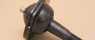
When repairing the steering and chassis, almost every car owner is faced with a problem (tire rod ends), which is quite problematic to solve without a special tool.
The reason is the design features of the named elements: their fingers have a cone-shaped shape, with which they enter the mounting sockets; over time, the place of this entry becomes dirty, oily, rusty, making the connection of the surfaces too dense, almost uniform, that is, one that cannot be separated by simple physical force . You need an assistant - a ball joint remover - a tool that greatly simplifies pressing out.
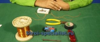
It is not difficult to become its owner: to do this, you need to go to the nearest auto store and purchase it there, or make a ball joint remover with your own hands using any of the methods presented below, which we have grouped depending on how the force is created in them.
Wedge type puller.
The simplest in its design, however, it also copes well with the task assigned to it. To make it you will need:
- take a small metal plate (enough size for a matchbox);
- using a grinder (angle grinder)/machine with an abrasive wheel, give it the shape of a wedge, the resulting workpiece in profile should take the shape of a triangle;
- Using the same grinder, starting from the upper corner of the triangle, you need to make a vertical cut in it at 2/3 of its height, a width slightly larger than the diameter of the ball joint pin;
- To make working with the tool easier, it is recommended to weld a metal rod to the middle of the base of the wedge, although you don’t have to do this if you don’t have such a rod at hand.
This is the kind of bracket you should end up with.
Then it's a matter of technique:
- insert the wedge you just made between the ball body and the eye;
- Hitting the rod (the base of the wedge) with a hammer, hammer in the homemade support puller until the finger pops out of the socket.
IMPORTANT!
When using this type of puller, there is always a risk of damage to the boot, so this tool can only be used in the event of a planned replacement of tips or supports. If the repair of the steering mechanism or suspension does not require such a replacement, it is better to abandon the “wedge” type puller.
Screw puller for removing ball pins
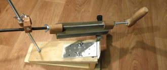
The main parts of the puller are made of steel strip with a cross-section of 18×3 mm and a total length of 460 mm. A round rod with a diameter of 18 mm is also suitable, but it needs to be modified: parallel edges with a distance of 13 mm between them should be milled or filed on opposite sides. To make a puller, you will need, in addition to the usual tools (a hacksaw, files, pliers, etc.), a grinder and a welding machine.
The design of the puller is simple and clear from the drawing and photographs.
The bar (upper part) is welded from two strips with a cross-section of 18×13 mm (although you can choose one of the same dimensions). The length of each strip is 95 mm. In the strip, almost in the center, there is a threaded through hole M12, and at the end there is a groove cut out 20 mm long, 13 mm wide and 2 mm deep for a fixing screw M12x55 (so that the strips do not rotate relative to each other). The wedge fork (lower part) is welded from three strips: two strips 95 mm long at the edges, in the middle there is a strip 55 mm long. On the workpieces at the welding points, we first remove a 3x45° chamfer along the entire length. Welds should be tapped and cleaned.
From the bottom of the front side of the lower fork we make a bevel, getting a one-sided wedge. Again, almost in the center, as in the bar, we make a through threaded hole M12, and at the end - M10 - for a fixing screw M 10x55.
And the last part is a sleeve 40 mm long with an internal and external diameter of 13 and 18 mm, respectively. The bushing can be replaced with a set of M14 nuts.
The operating principle of the puller is simple. We unscrew the nut from the ball pin and place the fork under the lever, while the bar rests against the end of the ball pin. Use the fixing screw to adjust the height. We tighten the power screw all the way with force, but you should not overdo it (tighten it too hard), it is better to wait a little - the finger may come out of the conical hole of the lever on its own. If necessary, hit the top of the fork with a hammer.
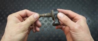
Puller directly for ball joints.
Used for cars (Citroen, Peugeot) whose ball joint is screwed into the lever. And since it is screwed in and not pressed in, it is impractical to use the above tool options; you need a special puller, which we suggest you make from an 8-centimeter thick metal pipe for 2”.
- At one of the ends of this pipe, equidistant from each other, using a grinder or a hacksaw, make 4 rectangular tenons 5x7 mm.
- At the second end, using the same tool, again, cut slots equidistant from each other to a depth of 3 cm so that you end up with 8 petals.
- Use a hammer to slightly bend these petals towards the center of the circle, thereby reducing its diameter.
- Take a 24mm nut and weld it to the narrowed side of the workpiece. The DIY ball joint remover is ready.
It’s simple to use: put it on the support so that the spikes fit into the existing grooves of the ball body, then use a 24mm wrench to turn the welded nut, thereby removing the suspension element you need.
How to remove a ball joint without a puller? When it's not at hand
Quite often, car enthusiasts are interested in how to remove a ball joint without a puller. This need may arise for various reasons. Most often, the existing puller does not fit the given car model. Although the principle of mounting the support is the same, the overall design of the suspension may be different. Therefore, it turns out that the existing puller simply cannot get to the part. Also, many novice drivers do not have some equipment available. You should not go to a service station due to the lack of a puller; again, you can do without it. In addition, there should not be any negative aspects.
Video.
Every self-respecting car enthusiast should have in his arsenal all the necessary equipment for quick and convenient removal of individual components of the car, if he does not want to pay exorbitant prices to a car service for what is essentially a simple repair.
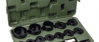
In this section of the catalog of our online hypermarket AvtoALL you can buy everything you need to dismantle large elements of your car. Pullers will allow you not to spend a lot of time on bearings, springs and connecting rods, depressurizers are indispensable when working with valves, and extractors will help solve problems with rusted or damaged fasteners (studs, bolts, etc.). They also sell inserts, mandrels, grips, expanders, clamps, spreaders and other tools of this type. You can buy them either individually or in a ready-made set, saving up to a third of the amount.
When carrying out repairs to the chassis and steering, there is almost always a need to remove ball joints or tie rod ends.
The peculiarity of these structural elements is that the support pin or tip has a conical shape, with which it fits into the seat.
During operation, the fit density increases so much that the surfaces of this joint practically stick to each other.
Additionally, moisture can get between the finger and the socket, causing pockets of corrosion that further seal the connection.
Therefore, to remove ball joints or tips, special pullers are used that allow you to press out the pin with minimal effort.
Wheel hub puller
The second example is how pullers make it easier to repair the chassis of cars. Russia's vehicle fleet, after the decline in sales during the crisis years of 2008–2009, is quite old, despite the revival of sales of commercial vehicles in 2010–2011. When carrying out repair work on the chassis of old and neglected vehicles, repairmen are often faced with the problem of dismantling wheel hubs. Disassembling this unit requires skill, accuracy and is complicated by the significant weight of the parts. This problem is especially acute when it comes to the hubs of truck drive axles. To make the work easier, special devices are used. For example, in the product line of the German company Kukko there is a fairly simple but functional KS-10G puller with a hydraulic drive. Its kit includes: a hydraulic cylinder with a manual drive, developing a force of 10 tons, forged pulling cones with a diameter of 300 and 350 mm and six power, again forged, brackets for attaching the device to the wheel studs.
Puller type - WEDGE
The simplest puller is the so-called “wedge”. It does not belong to any type of removable mechanism, but at the same time it is a fairly effective device for pressing out.
To make it, you only need an angle grinder (“grinder”), you can also use a machine with an abrasive wheel.
The blank will be a metal plate the size of a matchbox.
First, it is necessary to give the workpiece a wedge shape, for which we grind the metal with a grinder or machine so that the profile of the plate looks like a triangle. Then, using the same “grinder”, we make a cut in the middle 2/3 of the length of the workpiece from the side of the apex of the triangle, that is, from the thin side of the wedge. The width of the cut should be slightly larger than the thickness of the support pin, that is, you should get a kind of bracket.
If desired, you can weld a metal rod to the bracket, which will make it easier to work with the wedge in the future.
Pressing out a finger with a wedge is very simple. It is installed in the gap between the eye and the support body. And then the wedge is simply driven in with a hammer, which leads to the finger popping out of the socket.
The disadvantage of the wedge is that the boot will be damaged during the pressing process. Therefore, the wedge can only be used when replacing supports or tips.
If the suspension and steering mechanism are being repaired, which does not involve replacing the ball elements, it is better not to use a wedge.
Lever pullers.
Lever pullers are a tool consisting of a pair of levers connected to each other in the middle. They also have a coupling bolt on one side. In the process of acting on the ball joint, this bolt is unscrewed, bringing the ends of the levers together, one of which is located between the support and the eye, the second - under the finger.
Such pullers are also quite effective, but they are larger in size, so they may not be applicable everywhere.
Screw release mechanism
The second type of removable mechanism, which can be made from improvised means, is a screw release mechanism. It is perfect for replacing ball joints of classic VAZ models.
A special feature of the suspension design of these cars is that the upper and lower supports are located symmetrically to each other and the distance between them is not large.
It can be made at home only if you have a drilling machine, or you will have to go to a lathe. This puller consists of only two parts.
To make it, you will need a square or hexagonal rod with 17 or 19 key edges, the length of which is 7 cm. Using a drilling machine, we make a hole in this rod and cut a thread for a bolt of 8. Screw in the bolt and that’s it - the puller is ready.
Let's look at how it works using the VAZ-2107 as an example. To press out the upper support, you need to unscrew the lock nut, but not completely, you do not need to remove it. Then we install the manufactured puller between the pins of the supports with the bolt screwed in until it stops.
To squeeze out the finger, we take two keys - with one we hold the manufactured body, and with the second we unscrew the bolt until the finger falls off the socket. After replacing the upper support, we do the same, but with the lower one.
Screw pullers.
The force in these types of pullers is created by screwing the bolt into their body: the tool body is put on the eye of the ball joint, the bolt rests on the pin and, when screwed, presses it out of its seat.
These types of pullers are quite compact, therefore they are considered universal, that is, suitable for any car, although such mechanisms are most popular among VAZ owners.
Let's look at how to make a ball joint remover with your own hands using examples of screw options.
Option No. 1 – screw expansion.
- Take a 7-centimeter 4- or 6-sided rod with 17 or 19 key edges.
- Using a drill tank, make a hole inside its body and cut a thread for an M8 bolt.
- Screw this bolt into the hole prepared for it. The puller is ready.
Let us explain how it works using the example of pressing out the upper ball joint of the “seven”.
- Unscrew the lock nut. We unscrew it, but do not remove it.
- We install the made puller between the pins of the supports, the bolt in it is screwed in until it stops and the head rests against the pin that needs to be pressed out.
- We take 2 keys: with one we hold the puller body, with the second we unscrew its bolt. Unscrew until the support pin is pressed out of the socket.
If it is necessary to dismantle the lower ball, all actions are performed in the same way, only with the puller turned upside down.
Option No. 2 – screw L-shaped.
- Take a 15-17 cm round metal rod with a diameter of 10 mm or more. Using a vice and a hammer, bend it into an “L” shape (the length of the short arm should be 5 cm).
- Cut a thread on the long arm of the workpiece and select a nut for it.
- Take a metal plate half a centimeter thick and cut a hole in it for the support pin using the wedge puller technology (it will be given below).
- On the thickened part of the wedge, opposite the slot, make a hole for the L-shaped blank and insert the long part of the rod into it, only after that screw the nut onto the “improved” rod. Do not tighten too much - the wedge-shaped plate should move well.
- Insert the plate into the gap between the eye and the support. The short arm of the L-shaped element should rest against the finger.
- Start tightening the nut and do this until the pin is pushed out.
Option No. 3 - a screw puller of ball joints made from a corner.
- Take a 7-8 cm metal corner, half a centimeter thick, maybe a little less.
- Make a cut on one side; with this cut, the tool will be attached to the eye.
- From metal plates equal in thickness to the metal of the corner, cut out 2 identical triangles and weld them on the sides of the corner.
- Take a 17 nut, select a long bolt for it, weld spacers to this nut on both sides, they will help in the future to position the puller bolt on the same axis with the support pin.
Next, weld this entire structure to the corner perpendicular to the cut so that the nut hole is directly opposite the cut.
- Screw the bolt into the fixed nut and press out the pin using the technology described above (in other types of screw pullers).
As you can see, to create a ball joint remover you can use almost all available materials, the main thing is to understand the principle of operation, the drawing will help you:
Replacing the lower ball joint VAZ 2106-2103
Replacing the ball joint with pullers, a few nuances, tips in the process.
Homemade ball joint remover. Pullers for ball joints and steering rods.
Screw L-shaped
The third type of removable mechanism, which you can make yourself, is also a screw mechanism, but it has shown itself to be excellent and allows you to work on any car.
To make it you will need a round metal rod with a diameter of at least 10 mm and a length of 15-17 cm.
From it you need to make an L-shaped blank with a shoulder length of 5 cm. That is, we take a rod, measure 5 cm on it, clamp it in a vice and use a hammer to bend it 90 degrees.
We cut a thread on the long part of the workpiece and select a nut.
Screw made from angle
Another screw puller can be made from a metal angle and a welding machine.
To do this, take a corner with sides 7-8 cm and the same length, and a thickness of 0.3-0.5 cm.
We make a cut in one of the sides to secure the mechanism to the eye. From sheet metal 0.3 cm thick we cut out two triangles that will act as braces. They need to be welded on the sides to the corner. This will significantly increase the strength of the structure.
We take a 17 nut and a long bolt for it. We weld the nut itself perpendicular to the cut so that its hole faces the cut.
So that in the future the bolt can be easily positioned on the same axis with the pin, before securing the nut by welding, a spacer must first be welded onto the corner.
All that remains is to screw in the bolt and the puller can be used.
These are the simplest types of removable mechanisms that you can make yourself.
In general, there are a lot of options, and with a little imagination and basic knowledge of plumbing, you can easily come up with and make your own puller.
We offer some drawings for viewing.
Exclusive
Each manufacturer of special tools and equipment has its own original developments that make it possible to simplify the most common operations for the repair and maintenance of rolling stock. This reduces their execution time and ensures high productivity. For example, Kukko engineers designed the KS-204-30 puller, designed for dismantling brake ratchets with automatic clearance adjustment manufactured by well-known companies. They are installed on most models of commercial vehicles. The peculiarity of the device is the presence of a transverse adjustable clamp designed for rigid fixation of the gripping paws. It allows you to clearly fix the ratchet before dismantling, which lasts a matter of seconds, despite the absence of a hydraulic drive. The latter, by the way, is included in the list of options for this device, but, as practice shows, it is absolutely not needed.
- What should a ball joint remover be like for a car?
- What is this?
- Types of pullers
- How to replace a ball joint using a puller
- Puller selection
If you have ever been under a car, then you are familiar with ball joints. They are located symmetrically near the car wheel. This part tends to wear out, especially in our off-road conditions, and therefore requires regular replacement. On average, a ball can withstand from 15 to 120 thousand km. Have you been driving over potholes and heard a characteristic dull knock on the left or right? When you turn the steering wheel, you hear a squeaking sound, and you make an effort to turn the car into a turn? Does your car start to wobble on a flat road? Is the front wheel slightly to the side? These are all signs of worn ball joints. Get ready to change them.
If you have a little knowledge of technology and decide to replace the ball joints yourself, you will have to purchase a special device that will greatly facilitate the task of removing the ball joints. You can, of course, do it without it, but with a puller things will go faster.
What is this?
Types of pullers
The very first puller was a wedge. They hammered it between the socket and the ball head until the ball pin separated from the socket. But this old-fashioned method can only be used for completely worn balls, because the rubber boot breaks during the knocking out process. There are screw pullers that are fixed to the center of the pin by the conical protrusion of the puller screw. All that remains is to tighten the fine-threaded screw with a wrench - and the ball pin will fall out, but the boot will remain intact.
There are pullers with a fixed hook . If the power of the puller is clearly not enough, then you can tap directly on the hook - and the stuck finger will give way. The power nut of such pullers is located at the bottom, which allows easy access to the wrench. These pullers are most often used by auto mechanics at service stations.
Tool for unscrewing the support
We will consider another type, which is used not for pressing out the finger, but for removing the support itself.
The fact is that on a number of cars (Peugeot, Citroen) the ball joint is screwed into the lever. Over time, the threaded connection sours, and it is quite difficult to unscrew this suspension element without a special tool.
But you can make the necessary puller yourself, rather than spending money on a factory one.
It is made from a 2" thick-walled pipe 8-9 cm long.
At the end of this pipe it is necessary to make 4 spikes with a width of 5 mm and a height of 7 mm, located at an angle of 90 degrees relative to each other.
That is, you should get 4 protrusions at the end of the pipe, evenly distributed around the circumference. This can be done using a hacksaw and a file, or with a grinder.
From the other end we make slits to a depth of 3 cm, dividing the circumference of the pipe into 8 parts.
Then we bend these petals to the center using a hammer, significantly reducing the diameter.
We take a 24mm nut and screw it to the end part, and then use a welding machine to seal the slots made.
It is quite convenient to work with such a puller - we put it on the support so that the spikes fit into special grooves on the support body.
In this case, the finger will pass through the manufactured tool, which will allow the locking nut to be screwed onto it, thereby securing the puller. All that remains is to use a 24mm wrench to unscrew the support using the welded nut.
The process of replacing tie rod ends. Introduction and instruments
It is necessary to approach the work of replacing steering tips responsibly, because driving with faulty tips can lead to dire consequences
You should also pay attention to the attachment of the tips themselves to the steering knuckles.
There are two types of attachment of tips to steering knuckles:
- installed with the pin down into the steering knuckle - closed type (with a closed outer casing and no nut on top);
- installed with a pin on top - open type (with an outer casing equipped with fixing nuts).
Depending on what type of tips are installed on the car, the set of necessary tools will also vary. So, for closed-type tips installed with the pin down into the steering knuckle, you will need a special puller, using which the tip can be easily “squeezed” out of the steering knuckle. Some craftsmen do without a puller, using a hammer, but it is better to refrain from such manipulations.
So, to replace the work you will need the following set of tools:
- jack;
- wheel wrench;
- a set of open-end wrenches and socket heads;
- WD-40 or other similar lubricant;
- brush;
- puller (for closed type tips);
- hammer (just in case).
The process of replacing tie rod ends. Execution of work
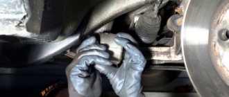
First of all, we repeat the manipulations indicated above (as when diagnosing the tips), namely, jack up the car on the required side and hang the wheel. Then use a wheel wrench to unscrew the wheel and remove it; access to the tip, steering rod and knuckle is free.
Now we use a brush and thoroughly clean the places of the fastening nuts on the rod and the tip, after which we apply WD-40 or any other liquid wrench to them. We wait a few minutes and begin to unscrew the nut on the steering rod side.
ATTENTION ! To unscrew the locking nut on the steering rod, you need to additionally secure it with a second key (there is a separate non-removable mount on the steering rod for this). The nut locking the steering tip should be unscrewed exactly 1-1.5 turns and remember its location
This is necessary to install a new tip and maintain at least approximate wheel alignment indicators.
Next, depending on the type of tips, unscrew the nuts securing them. With open-type tips installed with the pin facing up, everything is simple. It is enough just to unscrew the fastening nut, after which, by tapping the stud with a hammer and slightly rocking the steering knuckle, we remove the hinged part of the tip. After which all that remains is to unscrew the tie rod itself from the tie rod.
On closed-type tips (with a nut at the bottom), the process of removing the hinge part from the steering knuckle is very similar: first, unscrew the nut a little and insert the puller tongue in this place (between the nut and the knuckle). The lower part of the puller rests against the pin itself, and when it is twisted, it is as if the tip is being squeezed out of the fist. If there is no puller, then the nut must be completely unscrewed, and then using a hammer, begin to rock and tap the steering knuckle, gradually pulling the hinge part out of the knuckle. As soon as the tip is removed from the fist, unscrew it from the rod, this completes the procedure.
Now all that remains is to install the new tips in place, but before that you need to measure their length (relative to the old ones). Based on the obtained dimensions of the tips, you should tighten or vice versa - loosen the nut fixing the tip on the steering rod. Otherwise, the process of installing new steering tips is absolutely identical to removing them: we repeat everything in the reverse order and tighten all the nuts. The procedure is completed, after which you need to go to the stand and perform wheel alignment manipulations.
Like almost everything, the steering ends change.
Alternative method
Finally, we note that it is possible to press out the support pin or tip even if it is not possible to make a removable mechanism. But this method should be used only in extreme cases. To remove the finger you will need a pry bar and a hammer.
The pry bar is used as a lever and must be installed in such a way as to create a force to press the support or tip, for example, place it between the steering rod and the rack eye.
After creating force with the mount, it is necessary to apply powerful blows to the body of the eye with a hammer. If everything is done correctly, then after 2-3 hits the finger will pop out.
The disadvantage of this method is that the eye can be damaged due to shock loads, so it is advisable to use pullers rather than knock out the support.