Design and principle of operation of a band sawing unit
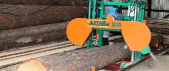
A modern band sawmill is a real automated complex
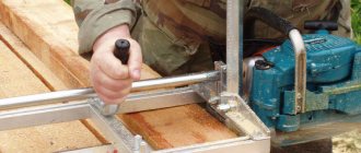
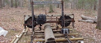
A band sawmill is a universal machine used for longitudinal sawing of logs to produce standard lumber - boards, timber, sleepers, carriages. Structurally, the unit consists of four main components: a band saw and its drive, a mechanism for moving the saw frame, a device for adjusting the height of the working blade and a clamping device for fastening the round timber. The sawmill is powered by an electric motor or internal combustion engine. Regardless of the power unit used, its power must ensure long-term operation of the equipment without overload. For a non-professional machine, an asynchronous electric machine with a power of 5 kW or a gasoline (diesel) unit of 6 - 8 liters will be quite sufficient. With. During operation of the machine, torque is transmitted to impellers (pulleys) with an installed “endless” saw blade up to 60 mm wide. Since the saw blade heats up and sags during operation, a hydraulic or spring-type tension mechanism is used.
Saw frame device
The longitudinal movement of the frame with the installed drive mechanism is carried out on rails installed on a solid concrete base. For this purpose, hardened steel rollers are mounted in the lower part of the unit body, the ease of rotation of which is ensured by closed ball bearings. The maximum length of the processed timber depends on the length of the rail guides.
The thickness of the wood layer cut from a log is determined by the height of the saw blade above the floor level and is regulated by a special unit, which includes a pair of threaded transmission and its drive mechanism. Thanks to the simultaneous rotation of two screws located at the edges of the carriage, its movement along the vertical guides is ensured and the saw does not warp.
Using a belt-type sawmill, you can obtain material of any thickness with minimal losses on sawdust
Shifting of the log during operation of the unit is prevented by a clamping device, which is assembled from a guide in the form of a round pipe and bushings with hooks installed on it with a large gap. The skew of the moving unit with installed “claws” leads to jamming of the device, which ensures the immobility of the round timber during processing. To better understand the operation of this device, carefully examine the illustration provided.
Jig operation
The operating principle of the sawmill is extremely simple. The log intended for sawing is placed in a bed between the rail guides. Then it is fixed with hooks, which are wedged with several blows of a hammer into the edges of the moving units. The carriage with the band saw is brought to the end of the round timber, after which the height of the working blade is set. After turning on the machine, the operator smoothly moves the saw frame along the rails, due to which the board is gradually cut to the required thickness. After reaching the other edge of the log, the cut lumber is put aside, the saw is raised and the unit returns to its original position.
Some sources suggest repeating the design of units in which the saw carriage is mounted motionless, and the cutting is carried out by moving a log laid on a movable platform. Perhaps such a scheme has a right to exist, but it must be taken into account that its implementation will require rails of double length.
The machine described above is a simple sawmill. If we talk about modern equipment, it almost completely eliminates manual labor. All operations, including moving the saw frame and adjusting the height of the band blade, are performed automatically, upon command from the control panel.
Video: Features of the band sawmill
Taiga-T-3 Band sawmill with electric drive. Purpose, scope
The portal band sawmill of the Taiga T-3 is designed from any type of wood, including hardwood, into a carriage, beams, edged, half-edged and unedged boards, as well as slats using band saws corresponding to various species and diameters of wood. Sawing is carried out with the log being processed stationary in a horizontal plane by moving the saw head along a guide path.
The Taiga T-3B band sawmill is equipped with a gasoline engine with a power of 20.8 hp. (15.5 kW) and its smooth start mechanism, which allows you to carry out work directly on the plot.
the Taiga T-3 band sawmill when sawing round timber: up to 14 m3 per shift, yield of useful lumber from 70% and above. Sawing a product with a length of 6.5 m and a diameter of up to 900 mm (one run) takes about 30-50 seconds.
Operating principle and design features of the Taiga T-3 machine
The Taiga T-3 band sawmill is a frame that moves on rollers along a rail track. The frame is moved manually by the operator.
Frame
The frame is a durable welded structure made of profile pipes mounted on rollers. A saw mechanism is mounted on the frame.
Rail track
The rail track is the base of the machine and consists of three sections (at the customer’s request, the rail track can be supplied with a large number of sections). Rail sections are channels welded together and installed on height-adjustable rail supports. To reduce noise during operation of the sawmill, calibrated wire is welded onto the channels.
When installing a sawmill in a new location, the rail track is aligned horizontally. The accuracy (variation in thickness) of sawn products largely depends on the accuracy of the installation of rail tracks.
Between the rails there are supports for the log, on which it is secured using stops and clamps.
Saw mechanism
The saw mechanism consists of two pulleys on which the band saw is pulled, a drive motor and a feed motor with a gearbox.
The saw mechanism is mounted on a traverse (saw carriage). The traverse is suspended on roller chains to the frame and moves up and down from a separate feed electric motor with a gearbox, ensuring adjustment to the required size of the material being cut. The amount of movement determines the thickness of the board cut from the log.
Drive and tension pulleys are installed on the traverse; a band saw tensioning mechanism is mounted between them. The drive pulley is connected to the electric motor by a V-belt transmission. The traverse is also equipped with movable and base support rollers, protective covers for pulleys and band saw blades.
The tension of the band saw is carried out using a hydraulic pump. The tension force of the band saw is controlled using a pressure gauge.
The tension force on the band saw when preparing it for work should correspond to the force recommended by the saw supplier.
The largest diameter of the processed log is 800 mm (with tilting)
Taiga T-3 sawmill has a powerful 11 kW engine, which allows you to saw almost any type of wood, including hardwood varieties.
The saw carriage has an electromechanical lift.
Saw pulleys (wheels) with a diameter of 600 mm made of cast iron significantly affect the tactical and economic characteristics of sawing, extending the life of the band saw.
Taiga T-3 sawmill can be equipped with a reinforced rail track and an electronic ruler.
The sawmill can be supplied either assembled or disassembled (modular architecture). 3 people are enough to load the machine. For transportation, small-tonnage transport is used (GAZelle - capacity 2-3 machines).
The Taiga T3 band sawmill allows you to cut a log into beams or boards of any thickness (from 1 mm), including edged ones, without readjustment.
The products obtained at the sawmill have a European cutting quality standard - uniform thickness (variation in thickness does not exceed 1 mm along the length of the processed material 6.5 m), correct cross-section (geometry) of the products, a clean surface, from which a minimum amount of chips is removed during further processing.
A robust frame with a reinforced structure allows the installation of additional sections of rail tracks to process logs longer than 8 m.
Design features of the Taiga T-3 SUPER machine (new, winter 2020)
Taiga T-3 SUPER sawmill is designed for high-quality sawing of logs with a diameter of up to 90 cm (with tilting) into various types of lumber.
The power of the electric motor of the saw drive is 11 kW, which is enough to saw even the hardest types of wood.
Cast iron saw pulleys (wheels) with a diameter of 600 mm are designed for the use of a wide range of saws with a width of 38-41 mm and a length of 4290 mm.
The pulleys are equipped with tapered bearings, which allows lubrication at least once every 3 months.
Duplicate band saw tension system: 1. hydraulic jack with a pressure gauge to control the degree of tension 2. mechanical method - nut/bolt tension using a torque wrench (supplied as an additional option, for an additional fee) Advantages of a double tension system - working condition of the sawmill, when inability to use one of the tensioning methods (weather conditions, repair breaks, professional qualities of the personnel, etc.).
A conveniently placed measuring ruler with the thicknesses of the most common types of lumber printed on it.
Improved rail track - an 80 mm channel with a 20 mm calibrated rod welded on its surface; thanks to this design, the sawmill moves much easier and faster than its analogues.
An increased durability of key mechanisms has been built in, which ensures stable operation in 2-3 shift mode. The sawmill operates stably at low temperatures and works with any type of wood, including hardwood.
Classic log screw clamps are characterized by their robust design and ease of use throughout their service life.
Delivery set of band sawmill Taiga-T-3
- Raising/lowering gearbox - 1 pc.
- Raising/lowering electric motor - 1 pc.
- Chains for fastening the saw mechanism - 2 pcs.
- Lifting/lowering force transmission chain - 1 pc.
- Electric power cable for the sawmill (the length of the cable corresponds to the full passage of the saw frame along the tracks) - 1 pc.
- String with fastenings for electric cable - 1 pc.
- Tank for saw lubricant fluid with drain system - 1 pc.
- Power control panel - 1 pc.
- Measuring ruler - 1 pc.
- Drive wheel - 1 pc.
- Driven wheel - 1 pc.
- Saw tension mechanism - 1 pc.
- Ruler of movable damper roller - 1 pc.
- Soothing rollers - 2 pcs.
- Saw catcher - 1 pc.
- Torque wrench for saw tensioning - 1 pc.
- Saw drive electric motor belts - 2 pcs.
- Support drive rollers of the saw frame - 2 pcs.
- Support driven rollers of the saw frame - 2 pcs.
- Leading pressure roller of the saw mechanism - 1 pc.
- Driven pressure roller of the saw mechanism - 1 pc.
- Saw lubrication system drain hose - 1 pc.
- Grease dispensers for lubricating wheel bearings - 2 pcs.
- Electric cable string support pipe (gander) - 1 pc.
- Spring for fixing the pressure scrapers of the driving and driven wheels - 2 pcs.
- Plumb lines for the saw carriage lifting/lowering chains - 2 pcs.
- Figured saw tension nut - 1 pc.
- Set of bolts/nuts/washers for fastening saw frame units - 1 pc.
- Tension bolt support bearing - 1 pc.
- Rubber locks for securing the lid - 2 pcs.
- El. fastening stud. engine - 1 pc.
- Measuring ruler fastening bar - 1 pc.
- Sawmill operating manual/passport/warranty card - 1 pc.
- Saw mechanism cover - 1 pc.
- Composite rail tracks - 3 pcs.
Electric cable tension stands - 2 pcs.
- Electric cable tension stands - 2 pcs.
- Overlays for rail tracks with a system for fastening logs and a system of stops (outermost) - 2 pcs.
- Overlays for rail tracks (intermediate) - 3 pcs.
- Log fastening system clamps - 2 pcs.
- Saw drive electric motor - 1 pc.
- Double-strand pulley - 1 pc.
- Engine mounting platform - 1 pc.
Saw frame - 1 pc.
Saw mechanism - 1 pc.
Box of parts and tools for assembly and maintenance of the sawmill - 1 pc.
Saw mechanism cover - 1 pc.
Composite rail tracks - 3 pcs.
Log fastening system - 1 pc.
Saw drive electric motor with pulley - 1 pc.
- Taiga T-1 * - 7.5 kW, log ø - 600 mm, pulley ø - 520 mm
- Taiga T-1 M - 7.5 kW, log ø - 600 mm, pulley ø - 520 mm (economy)
- Taiga T-2 - 7.5 kW, log ø - 800 mm, pulley ø - 520 mm (standard)
- Taiga T-2M - 11 kW, log ø - 800 mm, pulley ø - 520 mm (benefit)
- Taiga T-2M SUPER - 11 kW, log ø - 800 mm, pulley ø - 520 mm (best seller)
- Taiga T-3 - 11 kW, log ø - 800 mm, pulley ø - 600 mm (premium)
- Taiga T-3 SUPER - 11 kW, log ø - 800 mm, pulley ø - 600 mm (best seller)
- Taiga T-4 * - 15 kW, log ø - 1050 mm, pulley ø - 700 mm
- Taiga T-1B * - Honda internal combustion engine 13 hp, log ø - 650 mm, pulley ø - 520 mm
- Taiga T-2B - ICE "Lifan" 8.7 kW, log ø - 800 mm, pulley ø - 520 mm (standard)
- Taiga T-3B - ICE "Honda"/"Lifan" 15.5 kW, log ø - 800 mm, pulley ø - 600 mm (premium)
Modifications of Taiga series band saws
Taiga belt sawmills with electric drive
Taiga band sawmills, autonomous (with petrol drive)
* - equipment is no longer available
What you will need to build a sawmill
For those who think building their own sawmill is not a difficult task, let us say right away that creating a high-quality, efficient unit is not easy. And the point is not even that you cannot do without certain financial costs - as a rule, the budget of a homemade sawmill easily fits into the amount of 30 - 40 thousand rubles. Assembling a unit capable of producing high-quality lumber will require solving problems related to stability of operation, ensuring the strength of components and parts, setting up and adjusting mechanisms, making devices for sharpening a band saw and setting its teeth, etc. Are you not afraid of difficulties? Then check out what materials and tools you will need for the job.
As rail guides, you can use steel angles with a flange width of at least 50 mm, a channel or an I-beam. The main requirement for rails is their straight geometry. It must be borne in mind that any shortcoming of our miniature “railway” will affect the quality of the cut, since the tape blade will copy every unevenness, transferring it to the surface of the board. That is why the best option would be T, N or U-shaped rolled metal. Unfortunately, corners are most susceptible to bending during manufacturing and transportation. The most ideal case would be to use factory rails, for example, from narrow-gauge transport, which, with some luck, can be found at scrap metal collection points.
The rollers that provide longitudinal movement of the sawmill can be turned on a lathe and hardened. In some cases, the use of conventional ball bearings is allowed.
Excellent rollers are made from linear guides based on ball bearings, which can be found on sale. This solution cannot be called the cheapest, but there is no doubt about the reliability and durability of such a unit
Actually, the frame, saw carriage and bed for laying logs are made of square and rectangular profile pipes. It is best to use rolled metal with maximum wall thickness. This will provide the equipment with the necessary strength, since the operation of the machine is associated with variable dynamic loads.
For the mechanism for adjusting the height of the carriage (traverse), you will need guides made of steel pipes with sliders and two long screws with nuts. For these purposes, you can use parts from decommissioned screw-cutting lathes (unlikely, but never mind), mechanical presses, or threaded rods from a construction store (the most affordable, but least preferred option). You can also order the production of parts from a turner - it’s still unlikely to be possible without contacting a specialist. In addition, you will need a chain drive, which is often borrowed from the gas distribution mechanism of automobile engines. Alternatively, you can use a bicycle chain and sprockets.
Pulleys from old domestic combine harvesters of the Kolos, Niva brands and other agricultural machinery are best suited as impellers for the belt blade. By the way, you can also get shafts and bearing housings from there. Please note that the diameter of the guides must be at least 30 cm (optimally 50 cm), otherwise excessive mechanical stress will lead to cracks at the base of the saw teeth.
Pulleys from decommissioned domestic agricultural machinery can be used in the design of the band saw drive
There are designs of homemade installations with guide pulleys in the form of wheels from passenger cars. For skeptics, we note that such a homemade solution has a lot of advantages, starting from the possibility of using assembled hubs and ending with the fact that fine adjustment of the belt tension during operation can be done by inflating the tires.
You can buy a band saw new or used. It is best to have several blades in stock, which can be replaced with sharp ones as they become dull.
As for the tools that will be needed during the work process, every self-respecting owner should have one. In particular, you will need:
- welding machine;
- “grinder”, or, in professional language, an angle grinder;
- drill press or electric drill;
- a set of drills for concrete and metal;
- set of metalwork clamps;
- set of wrenches;
- hammer;
- pliers;
- fasteners (bolts, nuts, washers of various sizes);
- measuring instrument (ruler, caliper, tape measure);
- level (preferably laser type).
Don’t forget that you will need to prepare a strong, level foundation, so be prepared for concrete work - stock up on sand, crushed stone and cement, prepare a concrete mixer, tampers, formwork and a long rule.
The procedure for making a homemade band sawmill
There are certain recommendations regarding the question of how to make a band sawmill with your own hands. These include the following:
- It is important to choose the right location for installing the equipment. If an electric motor is used as a driving element, it is recommended to eliminate the possibility of increased environmental humidity to prevent a short circuit. For ease of processing logs, the area of the workshop or shed should be at least 18 square meters.
- The work of a band sawmill involves manual feeding of logs, the weight of which is quite large. That is why work on creating the structure in question begins with the manufacture of the frame. It must be stable and have an elongated shape. One part of the machine is designed to accommodate the main structural elements, the second for feeding the workpiece. The elongated part, where the log is located before processing, has rails that help move the workpiece. During production, a profile with a cross-sectional area of at least 5 centimeters is used. Particular attention is paid to the evenness and horizontal guides.
- The homemade product cuts the workpiece in a horizontal plane. That is why you should consider how the height of the saw will change. Various mechanisms can be used.
- In our case, an electric motor is used to transmit rotation to the main structural elements. When choosing an electric motor, it is taken into account what voltage it should be powered from (220 or 380 Volts), what power is needed, as well as the placement of the main fastening elements. It is recommended to choose a motor that is powered by a 220 Volt network and has a power of at least 2 kW. The power of the electric motor determines how productive the created machine will be. If you choose the wrong electric motor, it will overheat during operation.
3d model of band sawmill
The above points indicate the main points for the production of a homemade sawmill. You can make a band sawmill yourself at minimal cost. After all, you only need to buy or find an engine, pulleys and rollers, find a metal profile for the frame and a blade for sawing. The reliability of the design depends on the technical condition of all components and the quality of their connections. Therefore, before using the sawmill, you should check it carefully.
Preparatory activities
At the preparation stage, the optimal design is selected, the necessary calculations are made and drawings are developed. After this, materials and tools are prepared and a place for installation of the sawmill is arranged.
Design work, drawings
The construction of a sawmill begins with the selection of a production site. It has been experimentally established that this will require an area of at least 3x6 m in size. In any case, when planning the length of the working area, it is necessary to take into account the maximum size of the forest being processed. It is best if the unit is installed indoors or under a large canopy. In this case, you can work in any weather.
Then the number of angles (channels, I-beams) and profile pipes required for the manufacture of rail guides, stock and saw frame is determined. The distance between the rails is calculated by adding gaps of at least 0.3 - 0.4 m on each side to the maximum diameter of the log. In addition, it is necessary to take into account transverse reinforcements, which are installed between the rails every 0.8 - 1 m. Supporting elements for timber can be mounted on the same reinforcements, raising the bed to a height of at least 0.2 m above the level of the guides.
Sawmill diagram Drawing of a saw carriage Drawing of a sawmill Drawing of a sawmill Drawing of rail guides Drawing of a sawmill
Depending on the design, drawings of components are drawn up that will need to be turned on a lathe - rollers, screws, shafts, bearing housings, pulleys, etc. The design of a homemade sawmill is taken based on financial capabilities, availability of materials and individual components, so the exact design of the unit everyone does it independently. However, we provide diagrams and drawings of the sawmill and its individual components as an example. They can be used in your own developments.
Drawing of the tension mechanism Drawing of the roller Impeller assembly
Preparing the base
A properly made foundation will ensure the equipment’s stable linear characteristics during operation.
Since building your own sawmill is a serious matter, you need to approach it responsibly. Perhaps in the future the equipment will become not only a good help in the household, but also a source of additional income. Such important factors as the durability and reliability of the sawmill, the ease of operation and the quality of the resulting lumber largely depend on how strong and level the base it has.
The construction of a base slab is no different from the construction of a shallow floating or simple strip foundation. A lot has been written about it, so there is no need to dwell on the construction process in detail. Let us only remind you that you will need a cushion of sand and gravel, the thickness of the base is made at least 10 - 15 cm, and its strength is ensured by an armored belt made of steel rod with a diameter of at least 10 mm. In this case, significant variable loads will not lead to cracks or subsidence of the concrete slab.
Sawmill design
The organization of work is based on the block principle.
It involves various variations of the device, starting from the basic one, where the saw is fed manually, to the most complex units, when the saw is fed automatically, the cutting thickness is set, the electronic system is programmed, etc.
Components of the structure:
- to organize the movement of the saw blade, a frame with two guides is used;
- screw mechanism for lifting the belt;
- hydraulic or spring unit for tensioning the tape;
- driving and driven wheels (pulleys);
- wheel guard casing;
- tape holder;
- V-belt transmission;
- electric motor;
- rail for carrying out the movement of the band saw;
- eccentric clamps for holding the block (log);
- emphasis;
- tank with liquid for wetting.
To create a smooth, reliable product, it is necessary to make drawings according to which the entire structure will be assembled.
At the same time, the drawing must be studied and understood, otherwise you can simply lose not only time, but also money.
First, the bed (fixed part) of the machine is made, which has a U-shape.
It can be made from two channels, which can be replaced with two rails (in the absence of the first materials). If you use rails, they need to be installed so that the sole is on top.
The bed can also be made from corners (50x100 mm).
The height of the channel should be at least 14 cm, the length should be about 8 meters.
Holes need to be drilled along the entire length of the materials in increments of 1-1.5 m. After this, using pipes whose length is 25 cm, the channels need to be pulled together.
Threaded rods or bolts are used.
Next, you need to make racks of channels or pipes on which the structure is installed. The number of racks depends on the length of the sawmill, so for an eight-meter length it is enough to make 4 racks.
In this case, the structure is further strengthened with the help of braces, since it is necessary to achieve rigidity of the product. See drawing. Next, a mobile cart is assembled, the dimensions of which are set depending on the width of the frame, while the cart on both sides should be slightly larger (about 8 cm) than the frame.
The length of the mobile structure should be approximately 60 cm. Most often, the trolley is made of a steel plate, the thickness of which is 46 mm.
Next, looking at the drawing, it is necessary to install an electric motor to ensure the movement of the trolley. The circular saw is also attached to it.
A special steering wheel is installed on the side of the structure to provide control of the trolley.
The guides on the sides must be equipped with sprockets to which the control wheel is connected.
The entire structure moves using a tensioned chain, which prevents free movement of the steering wheel.
To prevent the log from jumping out during operation of the sawmill, it is necessary to make clamps that are made from pipes.
It is more convenient to use pipes whose internal diameter does not exceed 35-40 mm, since movable rods will be installed inside.
Clamps must be placed on top of the pipes. The metal corner is the material from which the clamps are constructed. Clamping cam mechanisms can also be installed.
If the clamping elements are less than 15 mm, then there can be no talk about the reliability of the design.
Next, the electric motor and saw are installed. You can do this at the beginning of work, or at the end. The main thing is to look at the drawings according to which the installation is carried out.
If you work on the engine at the end of the work, you must purchase it in advance so that the proportions of the entire structure are correct.
For the example under consideration (bed length is 8 m), the engine power must be at least 10 kW, and the saw diameter must not be less than 1 m.
Otherwise, the dimensions of the entire structure must be revised to smaller ones.
Instructions for making a sawmill with your own hands
As a working project, we will take a design with wheels from a passenger car, known for its simplicity and low cost. Since the correct and reliable operation of the saw unit depends on each element, we will consider in detail the manufacturing process of each unit, the nuances of assembly and configuration of the equipment.
Rail guides
Laying rail guides
When using corners measuring 50x50 mm as rails, they are not laid on one of the shelves, but with the edge angle facing upward. This will reduce wear on parts and provide increased structural rigidity. If you use rolled metal with a 100 mm flange for the guides, then such a corner can be installed in any position. It must be said that the most successful option is rails made from I-beams or channels, since they have increased rigidity even without being “embroidered” with the help of transverse elements. By the way, a square profile with a width of at least 25 mm is used as “sleepers”. The rail parts are connected to each other using electric welding. When installing spacers, weld a half-inch diameter pipe with devices installed on it for fixing logs (“claws”).
When performing welding work, you must ensure that the workpiece does not “lead”, which often happens when parts overheat. Most often, such troubles occur with corners and other thin metal products, so in this case it is better to use a semi-automatic welding machine that operates in a carbon dioxide environment.
If it is not possible to ensure the straightness of the rails during welding, then the installation of the transverse elements is carried out with a threaded connection. The guides are attached to the concrete base using anchor bolts.
Simultaneously with the installation of the rails, a bed for laying timber is constructed. To do this, vertical H-shaped posts with a minimum rod height of 10 cm and protrusions to prevent rolling of round timber of at least 5 cm in size are attached to the “sleepers.”
The bed for laying lumber can have any configuration
The nearest 3-4 crossbars are installed at a shorter distance - no more than 0.5 m. Thanks to this solution, in the future it will be possible to work not only with long pieces, but also with short workpieces.
Rollers
Both parts turned on a lathe and ordinary ball bearings can be used as rollers. In the first case, a hole must be provided for installing the rotation unit, and the wheels themselves are hardened. The second option involves installing one enlarged and two or three identical bearings on the axle. Of course, the parts are selected with the same internal size, and the shaft is machined with a thrust collar on one side and threads for attaching rollers on the other.
Wide rollers are good because any rolled metal can be used as rails, including channels and I-beams
Saw frame
The manufacture of the saw frame begins with vertical guides, of which two pieces are required. It is best to make the racks and sliders from steel pipes selected with minimal clearance. After this, a rectangular frame of the carriage is made, to the sides of which the upper and lower sliders are welded. Since impellers will be mounted on the lower cross member, it must be made of a rigid square pipe or channel.
Trying on guides and sliders
The body of the sawmill is not something complicated, since it consists of paired vertical and horizontal elements connected at right angles. A durable frame is made from a square steel profile with a width of at least 50 mm. Smaller rectangular metal can be used as spacers.
Welding the bed
The use of profile pipes will provide rigidity to the structure. If corners are used as structural materials, then their joints are additionally reinforced with steel braces with a thickness of at least 2 mm.
Rollers are installed at the bottom of the frame, having previously determined the distance between their thrust walls. It must match the width of the rail guides.
Saw frame assembled with guides and carriage
Carriage lifting mechanism. Photo gallery
Vertical movement of the carriage is ensured by a paired screw mechanism with manual drive and chain drive. The nuts are welded to the lower bushings (sliders), and the thrust part of the screw is mounted to the upper crossbar of the saw frame. The screws will rotate easily if you use suitable bearings as supports.
The drive for the saw carriage lifting mechanism is assembled with the drive and tensioner The upper assembly of the lifting mechanism The nut of the lifting mechanism is welded to the carriage bushing On the upper cross member the screw is installed in the bearing
To ensure that the lifting mechanism works without distortions, sprockets of the same size are installed on the shafts. After installing the chain, it is tensioned using a roller or fluoroplastic cracker. The drive of the flexible transmission is provided by gears of different sizes, one of which is rigidly connected to one of the screws, and the other is mounted on a separate shaft. The use of an oversized drive sprocket will allow you to quickly move the carriage along the guides. The fixation mechanism can be made of a spring-loaded pin, which, after adjustment, is installed between the chain rollers and fixed brackets. After assembly, the drive is equipped with a comfortable handle.
Pulleys
Manufacturing of hub adjustment unit
For pulleys, wheels and axle shafts are taken from a rear-wheel drive passenger car. To secure them to the bottom cross member of the carriage, you will need bearing units. It is best to order these parts from a turner - in this case it will be possible to make them adjustable, which will allow you to move the axes of the impellers to the sides. The fact is that during operation the band saw heats up and lengthens. If you don’t pull it up in time, it can fly off our “pulleys.” If you move them a couple of degrees away from the longitudinal axis, you can eliminate this danger.
Mounting the hubs on the saw carriage
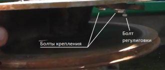
Adjustment units are sections of pipes, one of which is installed into the other with a gap of up to 5 mm. The inner clutch is also a housing for the axle bearings, and its alignment is ensured by screws installed on the outer collet.
Installation of the power unit and main drive elements
One wheel is mounted motionless on the carriage, supplying the shank of its axle shaft with a pulley. The other is mounted on a movable unit, which will pre-tension the saw blade. The installation of pulleys is not carried out horizontally, but with an offset of 2 - 4 mm in the vertical plane. The leveling of the band saw occurs due to the displacement of the cutting blade support unit. This structural element can be made of three ball bearings, like the rollers of a saw frame.
The saw blade support unit can be made from ball bearings
Installation of the band saw support unit. The device of its adjustment mechanism is clearly visible
After assembling and installing all components, the power unit is mounted on the unit. Rotation from the engine to the drive wheel is transmitted via a V-belt drive. Depending on the motor used, the belt is tensioned using a spring-loaded roller, if an internal combustion engine is used, or by shifting the frame with an installed electric motor. In addition, a protective casing is made that prevents sawdust from flying in all directions. At the last stage, a container with lubricating and washing liquid (LCF) is installed, the tube from which is connected to one of the cutting units.
Making a protective casing
Setup and launch
A small hydraulic jack can be used in the saw blade tensioning mechanism
After assembling the unit and checking the tightness of all bolted connections, a band saw is installed on the impellers, after tensioning which a test run of the sawmill is carried out. If the test switch-on is successful, then the engine is turned off and after the saw has completely stopped, the log is laid and fixed on the bed. The thickness of the first board is adjusted using the saw lifting mechanism, after which a test cut is made. The installation is turned off and inspected, a conclusion is made about the operability of the sawmill.
Homemade circular sawmill
Disc sawmills have received the greatest handicraft use due to their versatility and ease of manufacture. We will make a circular sawmill with our own hands. The most important thing is that we will need a circular saw - a disc larger than 500 mm (the larger the better). The propulsion device is usually an electric motor through a pulley that increases the speed.
1 — main sleeper (steel pipe 80x80x3, 5 pcs); 2 — lining (steel sheet, 40x10x1.22 pcs.); 3 — guide blade (steel channel No. 8, L1750, 4 pcs.); 4 - trolley (telpher carriage); 5 — bottom bracket (steel channel No. 18, 2 pcs); 6 - plate - base (stylish sheet s5); 7 — M20 bolt) (4 pcs.); 8 — Grover washer (4 pcs.); 9 — nut M20 (4 pcs.); 10 — three-phase asynchronous electric motor (220 V, 5 kW, 930 rpm); 11 — upper bracket (steel angle 45×45); 12 — circular saw blade; 13 — protective casing (steel sheet s2); 14 — steel pin (8 pcs.); 15 — circular saw hub (St5); 16 — thrust handle (water and gas pipe 3/4″); 17 — cut-off slab; 18 — thrust gusset (steel sheet s5); 19 — comb (steel angle 45×45, L400); 20 - log; 21 — M30 bolt; 22- split washer; 23 — retaining washer (steel sheet sЗ); 24 — thrust crossbar (steel angle 45×45); 25 — shortened sleeper (steel pipe 80x40x3, 6 pcs.); 26 — overlay for lengthening the blade (steel sheet 250x180x10, 2 pcs.).
A welded frame is prepared, a metal (less often wooden) plate with a slot for the disk is placed on the frame. The gaps between the disk and the plate are minimal. The saw shaft is attached to the plate from below on bearings and a pulley. The electric motor pulley and the saw are connected by belts (reinsurance when the saw jams) - a homemade circular sawmill can work!
one of the options for a homemade circular sawmill
To tension the belt, use the weight of the engine with the addition of weights. Make the supporting platform of the electric motor movable coaxially with the saw shaft, deflecting under weight in the opposite direction. The wheel of a working tractor with a drive to a saw pulley without belts is often used as a propulsion device.
The principles of cutting are the same as in band cutting - we feed the log to the cutting disc. After a disc cut, the surface of the lumber is of higher quality due to the speed of processing. Disc sawmills come in vertical and horizontal types - they are easier to use in mobile installations.
Tips for use
- Tension the saw blade correctly. Exceeding the permissible force reduces the service life of the tool. For control, you can use special devices. The saw should not be in operation for more than two hours, after which it must be dismantled and suspended for a day to relieve residual stress.
- Be sure to use belt lubricant. In warm weather, you can use water with the addition of detergents such as “Gala”, “Fairy”, etc., and in winter - a mixture of kerosene or diesel fuel with motor oil in a 5:1 ratio or lubricant for chainsaw chains.
- After finishing work, be sure to release the tension on the saw.
This will prevent fatigue phenomena from forming on its surface and will extend its service life. This is what it was all about - Work only with properly sharpened and set tools. If you have no experience in this area, you can use the services of specialized offices. As a rule, their representatives service more than one sawmill in your area.
- Do not work with freshly cut timber. Let it dry for at least one month. In addition, before work, clean the logs from dirt and sand, and even better, remove the bark.
Video: Band sawmill made at home
We hope we were able to convince you that building your own sawmill, although difficult, is quite possible. A self-made unit can work no worse than a factory sawmill only if you follow the recommendations of experienced craftsmen during the work process. Believe me, the care and scrupulousness shown will be reflected in perfectly straight cuts. Your site will acquire new, stylish buildings, built using warm and noble materials, obtained with your own hands.
- Author: Victor Kaploukhiy
Thanks to my varied hobbies, I write on various topics, but my favorites are engineering, technology and construction. Perhaps because I know many nuances in these areas, not only theoretically, as a result of studying at a technical university and graduate school, but also from the practical side, since I try to do everything with my own hands. Rate this article:
- 5
- 4
- 3
- 2
- 1
(44 votes, average: 4.4 out of 5)
Share with your friends!
Important Features
A homemade band sawmill has many advantages. Among them is the possibility of constant improvement and modifications, which makes it possible to more accurately “tailor” its characteristics to the growing requirements of the owner. For example, if you initially planned to cut logs into planks, you may soon need to start making your own lumber.
This design is assembled using a block-modular method. If you do not have practical experience and skills in constructing complex mechanisms and assemblies, start working with simple drawings. The mechanical drive version can easily be equipped with additional automation parts. Among them:
- Cut thickness regulator.
- Saw feed regulator.
- Programmer and many others.
Therefore, you need to understand the basic drawing and assembly instructions.
As mentioned above, a large number of modifications to sawmills are used today. When choosing a suitable solution, you must ask yourself in what plane you plan to make the cut. It is this aspect that indicates the placement of the working structure. The next question is to choose a single type or universal type of sawmill. For example, if you have to trim logs into separate segments, and not just the basic cutting of timber into boards, then it makes sense to choose universal equipment. It is very good if the working frame supports reinstallation.
It is no secret that logs processed by a band sawmill are characterized by large dimensions and impressive weight. In addition, when processing, the frame is subject to intense loads, so you must pay special attention to the stability of the band saw equipment. In this case, you don’t have to worry about the quality of the cut and the safety of workers.
Making a sawmill at home with your own hands is not as difficult as it initially seems. Many difficulties arise for people already at the next stage - preparation for operation . The biggest problem is setting up and sharpening the saw.
