Cut. Such complex simplicity.
Look at this photo and try to imagine what this stone might look like when cut in your ring:
I agree with the answer that it is possible to imagine, but. Difficult.
The process of cutting, that is, mechanical processing of a precious stone, consists of two main stages - cutting the stone to give it a certain shape and polishing its new surface. The cutting of any stone is not done at random, but is carried out according to a pre-thought-out and calculated scheme. The shape, size and location of the edges and angles between them are of fundamental importance. For each type of gemstone, these characteristics are calculated based on its optical and physical properties. The index of refraction, which is the most important indicator for identifying gemstones, remains the most important when designing a cut design.
The dimensions of the faces and the angles between them are calculated in such a way as to ensure optimal passage of a ray of light through the stone, both when the light is incident from the side of the crown (top of the stone) and when the light is passing from the side of the pavilion (cone). Since all stones have different optical characteristics, some types of cuts, ideal for, say, garnets, are absolutely not suitable for amethysts. On the other hand, the perfect cut for an amethyst will be just as good for a garnet. The refractive index of garnets is significantly higher than that of amethysts. A successful cut design for low-refractive stones remains equally successful for highly refractive stones. But not the other way around.
Now, thank God, it’s the 21st century, and we have moved away from prehistoric times, when we cut stones almost on our knees. True, since then a unique terminology has been established among cutters, and a cutting wheel used even on the most cutting-edge automatic machine is still called “lap”, or “knee”.
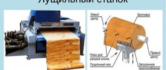
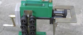
A cutting machine is a mechanism equipped with a cutting wheel drive, a working rod holder and the rod itself on which the stone to be cut is fixed. Depending on the complexity (and price), the machines are equipped with various types of devices, mechanical or electronic, manual or automatic, which control the given proportions - dimensions and angles - during the cutting process. The most modern machines are equipped with laser control of indices (numerical expressions in which the dimensions of the edges, their quantities and specified angles are encrypted). When working on such a machine, the skill of the cutter is expressed exclusively in a mathematical and design form. The more accurately and competently the indices are calculated and set, the more beautiful the stone will ultimately turn out.
An average cutting machine (with mechanical index control) looks like this:
And this is what a typical design project for a standard round brilliant cut looks like. As you can see from the post, this design is suitable for any gemstone with a refractive index of 1.540 and above and includes 57 crown and pavilion facets, as well as 16 mini girdle facets - the thin line separating the crown and pavilion.
And now - a few illustrations showing the stages of stone transformation during the cutting process:
First, the pavilion is cut, given its initial conical shape and the main edges are applied to ensure symmetry. Then the stone is given a “cylinder” shape, corresponding to the external planned size (diameter) and forming a circle or girdle plane, then secondary, additional faces are applied to the pavilion.
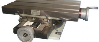
Now it’s time to cut the top part of the stone – the crown. To do this, the stone must be re-fastened. The procedure is extremely important - if the alignment is disrupted during the primary and secondary fastening of the stone on the holder rod, even by hundredths of a degree, the cutting design project becomes impossible, the symmetry and conjugation of the edges of the lower and upper parts of the stone is lost. For such an important procedure, a special mechanism was invented and used:
Next comes the cutting of the crown and the formation of the table (platform). First, the faces of the girdle and the main faces of the crown are combined, forming symmetry, then the remaining faces of the crown intended by the project are created. And finally, the stone is pressed against the cutting wheel at a strictly 90-degree angle, and the very top of the crown is cut off, forming a flat platform of a given diameter - a table.
The cutting is finished. The no less complex and responsible process of polishing the stone begins. The process is multi-stage, for which various polishing wheels and pastes are used for coarse, medium and fine polishing.. As a result, the stone that you saw in all the previous illustrations, a dark red garnet, takes on this look:
The changes that stones undergo during the polishing process from one stage to another can best be illustrated by a more striking example. The photographs show a freshly cut synthetic yttrium gadolinium garnet and the evolution of its appearance during the polishing process:
My cutting machine
I haven't looked at or visited this forum for a long time. Today I decided to take a look and, as usual, on autopilot, I entered “cut” into the search engine. And, to my surprise... and partly to my joy, I saw this topic. Despite the fact that I haven’t written online for a long time and don’t think this is advisable, still, in honor of such an event, and as an exception, I will break this rule...
…..
Collea!!! In general, I sincerely congratulate you on the machine... and cutting!!!
And now - on the substance of the topic. I looked carefully and read what is written here. For Ph.D. honey. sciences, etc. - excellent!!!* it’s clear that you didn’t make it with your own hands. this was done at best by “five-grade” students from not the best “school”... but if I’m wrong and you did it, then :good: * ...
For a professional, the maximum is a three plus... or a minus / on a five-point scale * I don’t take jewelry into the count. For it, and especially for a filigree... especially a “multi-story” one, as it is now fashionable to say, a separate thing is respect and respect /.
In general, the quadrant itself reminds me of the “calculations” from the “Lapidari Magazine” of the shaggy years, with the “abuse” of bronze, and negligence regarding the role of polishing in this matter...
Where did the locking plate on the housing of the mandrel lever go?) - Without it, this circuit does not work)... From the photo, it is quite possible - it was also made of bronze/or brass/. The lock of this locking plate itself is structurally an original idea.
I liked the splitter with the backlash removed by a spring, but I didn’t like the design of fixing the pressure bar with the axle. With such a design, it was necessary to “guess” the axis to this bar. But even there there would be some disadvantages.
Whatever one may say, this is what:
— there is no “trough” or fencing. well, no and no. and God be with him...;
- in this quadrant it is impossible to align the mandrel lever normal to the circle / and the “consumption” of the stand does not seem to be enough /... In any case, for this you need a circle of a larger diameter. But here, obviously, a 45-degree mandrel is used - according to which the “correction”/”reconciliation” is made**...** the fact that this is necessary is obvious from the stand-“protractor” assembly;
- if we take into account that the “protractor” does not interfere with lowering the mandrel lever to a horizontal position, and that the mandrel lever rotates freely and without play in these bronze bushings / or the bushing and washers, then - there is nothing else on it except a circle and a square grind it. and this was once again proven by the photo of your cut...*** in my opinion, this is a big minus because limits the possibilities of cutting fancy shapes and reduces the circle-square to a “banal” one...
As for the cut, I won’t say anything. Apart from the thorn, which is not quite brought to the point, you can’t make out anything. But, your statement that everything is “on point” - I have no right to question it because It’s very difficult to photograph such things, and “live” it will always look much better - than through the crappiest digital SLR.
Regarding the spindle, I won’t say anything because... there is no “input data”... - it works - and okay... And, there is nothing to shine “right and left”))). Judging by the toggle switch on the body, the machine is probably single-speed...
By quartz. This stone bothered me. I don’t know how diamond paste works on small surfaces, but on large surfaces it’s polished / fucking rock there)))/... One of these days I’ll try, following your advice, on a separate piece to polish a large area with diamond paste 1/0. But I think that in practice the large plane will heat up. And, if you’re warming up, then it’s not worth taking such a serious risk...
About the "Bible". This is more of a Primer for beginners in cutting. One and only of its kind. And nothing more. It is easy to read, just like many similar publications on cutting and gemology.
Regarding it is easier to buy faceted. Naturally, Asian consumer goods on the market are like dirt. And to compete with him is to sink to their lowest level...
Briefly and in general terms - that seems to be all. If it seems that I wrote something rudely somewhere, don’t blame me... I didn’t pursue any mercantile goals.
I won’t be too lazy to repeat myself again.Collega!!!
Once again, congratulations on the machine and the “publication” of this case!!! The fact that “your hands are itching for the cut” is good... In general, those who “got into this topic and delved into it” never give up cutting again. And this despite the fact that cutting in the post-Soviet space is more of a hobby than a business... in other words, in spite of everything and not thanks to :good:... including about your machine... what else... - Good luck and wishes to cut in for your own pleasure, from the heart and for the joy of your loved ones, acquaintances and friends... And of course, sometimes making a little money from all this doesn’t hurt!!! Modified April 6, 2011 by LAE71
Equipment for cutting stones
Special equipment is used for cutting stones: faceplates, cutting heads, cutting machines of various designs, cutting wheels, etc.
To cut, stones are first glued to the end of a wooden or metal mandrel and, pressed against a rotating faceplate, ground until one flat area is formed. Then the mandrel is turned and another area is ground. This procedure is repeated several times, obtaining a closed belt of edges around the perimeter of the stone.
Cutting heads
Many amateur and professional craftsmen use cutting heads in their work.
A rigid and durable cutting head allows you to fix the stone at any angle of inclination to the surface of the cutting wheel and at any angle of rotation to its axis.
On the right is a cutting machine: a - a support with holes for installing a holder; b - holder; c - octagonal collar; d – precious stone mounted in a holder; e - fixed collar guide.
In the design of the support sleeve, the angle of inclination is set by inserting the sharp end of the mandrel into one of the holes in the sleeve, and the angle of rotation is determined and maintained only by the hands of the cutter.
When the edges on the stone are obtained, the cutter changes the grinding wheel to a polishing wheel, on which all ground edges are polished
one after another until they become shiny.
The advantage of a mechanical faceting head is that it allows you to return to processing any facet.
The main components of mechanical cutting machines are:
- a metal base that connects all the units into a single whole and ensures precision;
- a spindle with a support disk, it ensures the rotation of grinding and polishing wheels;
- a cutting head that holds the stone and makes it possible to grind and polish at certain angles.
Lapidary machines
Cutting machines can be portable or stationary.
A good cut can be done even on a homemade machine, which consists of a vertical spindle, a shaft on ball bearings, and a stand with a quadrant of angular divisions. Cutting discs, grinding wheels, grinding and polishing faceplates are mounted on the spindle.
A fairly quick and economical cutting method is to use faceplates for working with free abrasive.
Some stones, according to master cutters, are processed better with them than on diamond wheels. The disadvantage of free abrasive is the dirt formed by its particles, which, if not dealt with, will create many problems.
For cutting, it is recommended to use silicon carbide powder on a lead wheel.
In addition, the following is used for cutting:
- diamond cutting wheels,
- diamond coated wheels,
- wheels with diamond-containing plastic coating, etc.
Polishing wheels
When all the edges of the stone are processed on a diamond wheel, a polishing wheel is used. A wide variety of materials are used to make a polishing wheel, from metals to leather. But most often, tin, plastic and wooden circles are used.
Wooden wheels can be of different types - for polishing girdles and for polishing large faces of stones.
Wax wheels are used to polish very soft stones and polish edges made of ordinary materials, which are difficult to process on standard wheels. Such circles are a metal disk covered with wax-impregnated cloth.
Aluminum, steel, copper, bronze and plywood circles are used as a base.
I wanted to buy a complete set of cutting machine for cutting expensive stones
Where and how, cheaper. Even used. Buy buy cutting machine
Hi all. Can anyone tell me where I can buy a cutting machine?
Machine for manual cutting of precious stones
The invention is used for cutting small precious stones of irregular original shape, such as diamonds, emeralds, sapphires, etc. The machine contains a horizontally mounted faceplate and at least one clamp for the stone being processed. The locking mechanism is capable of providing at least one linear and at least one angular movement. The invention makes it possible to reduce vibrations in the kinematic chain of the machine and thereby reduce the risk of chipping stones during cutting. 5 salary, 7 ill.
Technical field The invention relates to kinematic diagrams and design of small-sized (usually tabletop) machines, which are designed for manual cutting of predominantly small precious stones of irregular original shape, for example diamonds, emeralds, sapphires, etc.
BACKGROUND OF THE INVENTION It is well known that small stones weighing less than one, and often even less than 0.1 carats, make up the bulk of the total mass of precious stones to be cut, that such stones usually have an irregular (often plate-like and even needle-like) shape, and that automation cutting such stones is significantly complicated not only by the variety of their shapes and sizes, but also by minor defects that are noticeable only to highly qualified cutters. Specialists understand that high-performance cutting machines with numerical control, which are designed for in-line cutting of pre-classified stones by shape, are not suitable for processing these raw materials. and sizes of precious stones. Therefore, manual cutting machines are still manufactured and widely used. They usually employ highly qualified cutters. Their experience allows us to minimize cutting losses and give diamonds or other cut gemstones the most spectacular shape. Such machines must satisfy several difficultly compatible conditions, namely: have the smallest possible weight and overall dimensions, be as simple as possible in design and, accordingly, convenient to manufacture and use for cutting arbitrary precious stones, be as resistant to vibrations as possible to ensure accuracy of cutting and reduction of weight loss of precious stones during cutting, which are caused by chips due to collisions and “collapsing” of edges due to loose contact of the raw material with the faceplate, and, if possible, provide comfortable working conditions for cutters, including the lowest possible noise level and ease of access to the faceplate over its entire area. Fulfilling individually or some incomplete combinations of these conditions does not present any significant difficulties. In this case, the main attention is usually paid to improving the working parts of such machines and, to a much lesser extent, to improving the beds and drives, the resistance to vibrations of which mainly determines the quality of cutting. For example, from SU 683135 A1 a very simple small-sized device for manual cutting of diamonds is known. It has a support with regulators of its spatial position and a body-handle, which is pivotally connected to this support and carries a rotating head with a collet stone holder. When cutting, this stone is manually brought to the faceplate. The cutting accuracy using such a device is low due to play in the sliding bearing, which is made in the form of a bushing-axis, and vibrations of the faceplate. From SU 1754463 A1 and UA Patent 15714, a more advanced small-sized device for hand-cut precious stones. To connect the rotating head with the body-handle, a sleeve is provided, which is pressed into this body-handle and has conical supporting surfaces. The lower surface rests on the balls, forming a rolling bearing, and on the upper conical surface there are ring sectors pressed with a washer, which serve as a sliding bearing. The clamp for fastening the semi-finished diamond in the device is made in the form of a housing in which a spring-loaded rod is installed on the guides, capable of moving in a vertical plane and around its own axis. A pressure bar is installed on the rod, capable of moving in a horizontal plane. For adjustment at the cutter's workplace, the device is equipped with a horizontal position indicator and a level screw. However, even periodic sampling of the play in these bearings does not provide sufficient cutting accuracy due to unsatisfactory vibration resistance, even when using a massive plate as a base. Therefore, the described device requires periodic adjustment (sometimes even when processing one crystal), which reduces labor productivity. Further, from RU Patent 2056264 a machine for manual cutting is known, which has: a frame in which a faceplate is located, connected to a rotation drive, a stand, which is located on the frame, a holder, which is made in the form of a hinged link and a rod and installed on a stand with the ability to swing relative to it, a mandrel, which is located in the holder with the ability to swing perpendicular to the direction of swing of the holder, and a position regulator for the swing axes of the holder and the mandrel relative to the surface of the grinding wheel , which is made in the form of a carriage and a stone holder head with a mandrel position lock. In this machine, the carriage is located on a stand with the ability to move relative to the surface of the grinding wheel, pivotally connected to the holder link and serves as a carrier of the mandrel with the ability to move it perpendicular to the axis of the head holder hinge stone. This machine allows you to flexibly change the position of the stone holder head relative to the faceplate. However, its radial and axial runout can only be “compensated” by the skill of the cutter, which leads to his rapid fatigue. A machine for manual cutting of precious stones, which is known from UA Application 94107193, has: a frame with upper and lower traverses in which holes are made, quills with bearings that are installed in the traverse holes, a stone feeding mechanism for cutting, a spindle with a faceplate and an electric motor that is mounted on a damping suspension and connected to the spindle by a V-belt drive. This suspension has a rod that is mounted on a damping support and fixed to the floor. The upper cylindrical part of the rod is secured through a damping gasket with a clamp on the lower traverse, which is also equipped with a damper. As can be seen from this description, “calming” the contact zone between the faceplate and the stone to be cut is achieved by increasing the massiveness and bulkiness of the machine. However, connecting the electric motor to the lower traverse through a rod, even when using several means of vibration damping, does not exclude radial and axial runout of the faceplate with a corresponding increase in rejects during cutting, especially small gemstones of irregular initial shape. Acceptable simplicity of the design as a whole and sufficient stability of the grinding wheel (faceplate) vibrations are ensured in the design of the diamond cutting machine from J.DaviD-Antwerp-Belgium (see company catalog 1999, p. 175). This machine has a hollow bed with a load-bearing frame, which, in particular, has the form of a frame made of rigid rods of square cross-section with numerous cross-sections, a table fixed to this frame with a hole in the middle part, which, in particular, is made in the form of a polished lid stone (usually granite), a faceplate placed in the hole of the table and installed on the vertical shaft of the spindle unit, the body of which is rigidly connected to the frame of the bed, a faceplate rotation drive having an electric motor mounted on the bed, the output shaft of which is connected to the shaft of the spindle unit by a belt drive, and at least one clamp of the stone being processed, kinematically connected to the frame with the possibility of at least one linear and at least one angular movement relative to the faceplate. However, such a machine can only be stationary and, due to difficulties in accessing the faceplate, is inconvenient to maintain during manual cutting precious stones. In addition, minimization of the radial and axial runout of the faceplate in its design is ensured only by the rigidity of the load-bearing frame and the massiveness of the table. Therefore, when cutting small precious stones of irregular initial shape, unexpected chips are still possible. Essence of the invention The basis of the invention is the task of improving the kinematic diagram and the relative arrangement of parts to create such a tabletop, that is, small-sized and relatively light, machine for manual cutting of precious stones, which would provide a reduction vibrations in the kinematic chain and thereby reduced the risk of chipping when cutting small gemstones of irregular original shape. The task was solved in a machine for manual cutting of precious stones, which has: a hollow frame with a power frame; a table fixed to this frame with a hole in the middle part; a faceplate, which is installed in the table hole on the vertical shaft of the spindle unit, the body of which is rigidly connected to the frame of the bed; a faceplate rotation drive having an electric motor mounted on the frame, the output shaft of which is connected to the spindle assembly shaft by a belt drive, and at least one clamp of the stone being processed, kinematically connected to the frame with the possibility of at least one linear and at least one angular movement relative to the faceplate , according to the invention, the hollow frame is equipped with a rigid bottom with at least three damping supports in the lower part, the body of the spindle unit is rigidly connected to the said bottom, the shaft is installed in the body of the spindle unit on a ball bearing, the geometric center of which is located on the geometric axis of this unit and is fixed inside of the said housing from radial displacement by the lower and upper sliding bearings and from the axial displacement of at least one such sliding support with at least one radial protrusion and a corresponding depression, which is located above the ball bearing, and the drive motor is connected to the frame by an elastic hinge and is equipped with at least one damping support. The elastic connection of the electric motor with the frame and the independent installation of this motor and the frame with a rigid bottom on their own damping supports, in combination with the rigid fastening of the spindle unit body to the frame and the fixation of the spindle shaft simultaneously from axial and radial displacements, ensure very quiet rotation faceplates in a wide range of angular speeds. Therefore, the risk of chipping of processed stones is significantly reduced and the amount of waste is reduced. The same features make it possible to produce a small-sized tabletop cutting machine that is easy to transport and maintain. The first additional difference is that the elastic hinge is cantilevered to the frame by means of a linear rolling support, which is designed for vertical installation movement of the electric motor relative to its damping support. This fastening additionally weakens the influence of vibrations of a running engine on the faceplate of the machine. The second additional difference is that the upper end of the spindle assembly shaft is equipped with an upper flange, which serves as a support for the faceplate and is rigidly connected to the drum, the lower part of which serves as a driven belt pulley. This form of kinematic connection between the faceplate and the electric motor provides the simplest transmission of torque. The third additional difference is that the machine is equipped with two independent lever-joint mechanisms, each of which at the working end has a rotating head, which is equipped with a lock for the stone being processed. This allows you to most effectively select cutting modes for both diamonds and other precious stones on one machine. The fourth additional difference is that the first lever-hinged mechanism is suspended by means of a clip with a lock of the required position to a vertical stand fixed to the frame and has a console, to to which a lever is attached to a cylindrical hinge with a vertical axis of rotation, carrying a rotating head with a handle and the first lock of the stone being processed. This mechanism is most convenient for cutting relatively large stones (weighing >0.2 carats). The fifth additional difference is that the second lever-hinge mechanism is mounted on the machine table on a flat platform, on which a cylindrical hinge frame with a horizontal axis of rotation is fixed, and has a horizontal sliding lever, in which the shank of the fixed part is rigidly connected to the axis of the said hinge, and at the working end of the moving part there is a rotating head with a second clamp of the stone being processed and a handle; and an intermediate support, which is rigidly connected to the movable part of the sliding arm and is mounted to slide relative to said platform. This mechanism is most convenient for cutting small stones (weighing <0.2 carats). Brief description of the drawings The essence of the invention is further explained by a detailed description of the design and operation of the machine for manual cutting of precious stones with reference to the attached drawings, which are shown in: FIG. 1 - general view of the machine from the front (showing the position of the spindle assembly and faceplate in the frame and the drive belt with dashed lines); Fig.2 - general view of the machine from above; Fig.3 - general view of the machine from the side (with the side wall conventionally removed); Fig.4 - attachment point for the electric motor to the frame; Fig.5 - spindle assembly in longitudinal section; fig. 6 - one of the possible lever-hinged mechanisms for moving the gemstone retainer relative to the faceplate (with a vertical stand); Fig. 7 is another possible lever-hinged mechanism for moving the gemstone retainer relative to the faceplate (with a telescopic lever). The best embodiments of the invention The proposed machine for manual cutting of precious stones (see Fig. 1) has: a hollow frame 1 with a power frame described below , a flat horizontal table 2 with a round hole in the middle, which is usually made of natural stone, such as polished granite, and is fixed to the said frame frame 1, a horizontal faceplate 3, which is installed in the hole of the table 2 on a vertical spindle assembly 4, which is rigidly connected with the power frame of the frame 1, a drive for rotation of the faceplate 3, which includes: - a predominantly brushless DC electric motor 5, which is mounted in the rear part of the frame 1 and is equipped with a power supply and an operating current regulator, not shown in the drawing, - usually a flat belt drive 6, in which a belt is used made of an elastic material, for example polyurethane, and - the specified spindle unit 4 - and preferably two independent lever-joint mechanisms 7 and 8 for manual movement of the latches 9 of the stones being processed. In this case, the mechanism 7 is installed on a vertical stand 10 with the possibility installation reciprocating movement, and the mechanism 8 has a horizontal telescopic, that is, sliding, lever 11 with an intermediate support 12. Each of these mechanisms 7 and 8 is capable of providing at least one linear and at least one angular movement of its own clamp 9 of the stone being processed relative to the faceplate 3. The continuation of the table 2 in the front part of the machine is the inclined plate 13 (see. figures 1, 2 and 3), which serves as a support for the hands (especially the elbows) of the cutter. This plate 13 typically tapers in a top-to-bottom direction (see Figures 1, 2) and typically has (see Figure 3) at least a single layer of soft covering of a suitable material such as artificial leather with an elastic lining. Typically, to the right of this plate 13, in a not particularly designated side wall, there is a machine control panel 14. The bed 1 (see Fig. 3) is necessarily equipped with a rigid bottom 15, which serves as the basis of its load-bearing frame. The other parts of this frame are at least two (front and rear and/or left and right side) rigid load-bearing walls 16, which in the upper part are rigidly connected to each other by a table 2. Instead of the load-bearing walls 16 or along with them, in the load-bearing frame of the bed 1 particularly rigid racks made of suitable rolled profiles, not shown, and rigid additional connections between such walls 16 and/or racks may be included. The rigid bottom 15 of the frame 1 (see figures 1, 3) is equipped with at least three damping supports 17. The same the support 17 has an electric motor 5 in the lower part (see Fig. 3). These supports 17 can be equipped with well-known and therefore not particularly shown level regulators. The electric motor 5 (see Fig. 4) is connected to the frame 1 by an elastic hinge 18, which provides relative freedom of angular deviation of the geometric axis of the shaft 19 of this electric motor 5 and the drive pulley 20 of the belt drive 6 from the position “parallel to the geometric axis of the faceplate 3” and additionally dampens noise. As can be seen in figure 4, the elastic hinge 18 can be made in the form of two bolted plates and a spacer made of a suitable elastic material, for example microporous rubber, between them. In the elastic hinge 18, which is shown in figure 4, one of the plates is bent so that its cantilever protrusion serves as a lining for the end of the electric motor 5, and the second plate is made flat. It is clear to specialists that this form of execution of an elastic hinge 18 is not the only possible. It is necessary that this hinge 18 is console to be connected to the chosen element of the power frame, for example, to one of the hard -loading walls 16 of the village 1, through the linear support of 21 rolling, which serves for for vertical installation movement of the electric motor 5 relative to its damping support 17. Spindel node 4 (see Fig. 5) has: the hollow case 22, which is strictly connected with the hard bottom of the 15th bed 1, the shaft 24, which is installed in case 22 on the ball of the ball of the ball 25, the geometric center of which is located on the geometric axis of the spindle unit, the lower and upper bearings of the 26 sliding, which are tightly pressed into housing 22, tightly cover the shaft 24 and fix it from radial displacement, at least one support 27 sliding with at least one ring the radial protrusion and the corresponding by the ring hood, which is located above the ball of the ball and captures the shaft 24 from the axial displacement (despite the fact that the ring cavity is usually made in the body of the shaft 24, and the ring protrusion can be made on the cut -out liner between the upper emphasis of the ball of the ball of the ball and the lower end of the lower bearing 26 sliding), the upper flange 28, which serves as the support of the planes 3, is rigidly connected to the upper end of the shaft 24 and is strictly associated with the drum 29, the lower part of which serves as a led belt of the belt transmission. VAL 24 relative to flange 28 is advisable to use the spacerly 30 or not shown in the transverse cross-section or not shown in the form and purpose of the spacer nut. The top sliding bearing 26 is usually fixed from the axial displacement of the composite cover 31. The first lever-chanier mechanism 7 (see. Figure 6) usually has: a clip 32 with a predominantly screw latch 33 for vertical movement and installation relative to the counter 10, the console 34, to which a 36 -vertical roller is connected on a cylindrical joint 36, a rotary 36 head 37 with a handle 38 and a handle 38 and a handle 38 and a handle 38 and The previously mentioned first fixer 9 of the processed stone. The second lever-screen mechanism 8 (see Fig. 7) is mounted on the table 2 on the flat platform 39, on which the clip of cylindrical hinges 40 with a horizontal rotation axis is fixed. This mechanism 8 has the previously mentioned: horizontal telescopic (sliding) lever 11, in which the shank of the fixed part (usually the rod) is rigidly connected to the axis of the specified hinges 40, and at the working end of the mobile part, a rotary head 41 with a handle 42 and an intermediate support 12, is installed. which is strictly connected with the mobile (usually tubular) part of the sliding lever 11 and is installed with the possibility of sliding relative to the platform 39. As it is clear from the drawings and the description of the structure, each of the mechanisms 7 and 8 is able to provide at least one linear and at least one angular movement its own latch 9 of the processed stone relative to the plank) in the conclusion that the working surfaces of the leading pulley 20 and the driven pulley on the drum 29 have a convex barrel shape and are limited to the drawings in the upper and lower dimensions, but especially not indicated by the beams. This prevents the distortions and sliding of the flat -coating belt 6. Drown -handed stones are manually limited on the described machine as follows. After the installation of the machine on a suitable base, which usually serves a strong stable table, is fixed in one of the latch 9, which is subject to processing and the drive is included. If the first lever-screen mechanism 7 is used for cutting (see Fig. 6), then taking into account the growth and length of the robber's hands, the latch 33 is weakened and move the clip 32 relative to the rack 10 in the required position, after which the latch 33 is screwed until the stop. Further by turning the console 34 relative to the counter 10 and the lever 36 relative to the console 34, the head 37 with a latch 9 of the stone to the selected section of the planhayba 3 and the handle 38 bring the stone to contact with the planhaba 3. If the cutting use the second lever-shared mechanism 8 (see FIG FIG. .7), then the mobile part of the lever 11 is raised by turning relative to the axis of the hinge 40 and put forward to the selected section of the Planes 3. Next, the lever is lowered so that the intermediate support 12 will again come into contact with the platform 39. Then the head 42 is rotated by the head 41 with the stone fixer 9 in the required position and, constantly maintaining the contact between the intermediate support 12 and the platform 39, the given line is applied to the stone. After the application of each given face, the stone is strengthened in the latch 9 in the new position and the processing is repeated until the cut is completed. The industrial applicability of the proposed machine for manual cut Precious stones allows you to fulfill all the requirements that were indicated at the beginning of a review of the level of technology, namely: it has very insignificant mass and dimensions, simple in design, is convenient to manufacture and use arbitrary precious stones for cutting; It is very resistant to vibrations, which ensures the accuracy of cutting and reducing losses, which are caused by chips of precious stones due to collisions and “flooding” the faces due to loose contact of raw materials with a pattern, and provides free access to the planhabe along its entire surface, convenient support. For the hands of cutters and low noise. Comfortable conditions contribute to a noticeable increase in labor productivity with manual cutting of precious stones.
Claim
1. A machine for manual cutting of precious stones, containing a hollow bed with a power frame, a table fixed to the frame with a hole in the middle part, a faceplate installed in the table hole on the vertical shaft of a spindle assembly, the body of which is rigidly connected to the power frame of the bed, a faceplate rotation drive with an electric motor mounted on the frame, the output shaft of which is connected to the shaft of the spindle unit by a belt drive, and at least one clamp of the stone being processed, kinematically connected to the frame with the possibility of at least one linear and at least one angular movement relative to the faceplate, characterized in that that it is equipped with a rigid bottom mounted on a hollow frame with at least three damping supports in the lower part, a ball bearing, upper and lower sliding bearings, at least one sliding support with at least one radial protrusion and a corresponding recess and an elastic hinge, in this case, the spindle unit housing is rigidly connected to the specified bottom, the vertical shaft is installed in the spindle unit housing on a ball bearing, the geometric center of which is located on the geometric axis of this unit and is fixed inside the specified housing from radial displacement by the lower and upper plain bearings, and from axial displacement - at least one sliding support, the cavity of which is located above the ball bearing, and the drive electric motor is connected to the frame by an elastic hinge and at least one damping support installed below. The machine according to claim 1, characterized in that it is equipped with a linear rolling support, which serves for cantilever connection of the elastic hinge to the frame for vertical installation movement of the electric motor relative to its damping support.3. The machine according to claim 1, characterized in that it is equipped with an upper flange and a drum, wherein the upper flange is rigidly connected to the upper end of the spindle assembly shaft, serves as a support for the faceplate and is rigidly connected to the drum, the lower part of which serves as a driven belt pulley.4. The machine according to claim 1, characterized in that it is equipped with two independent lever-joint mechanisms with a rotating head and a lock for the required position of the stone being processed at the working end of each of them.5. The machine according to claim 4, characterized in that it is equipped with a holder, a vertical stand, a handle and a console with a cylindrical hinge and a vertical axis of rotation, while the first lever-hinge mechanism is suspended by means of a holder with a clamp for the required position of the stone being processed to a vertical stand fixed to the frame , to the console of which a lever is attached on a cylindrical hinge with a vertical axis of rotation, carrying a rotating head with a handle and the first lock for the required position of the stone being processed.6. The machine according to claim 4, characterized in that it is equipped with a flat platform installed on the table, a cylindrical hinge cage with a horizontal axis of rotation and an intermediate support, while the second lever-hinge mechanism is mounted on a flat platform on which the cylindrical hinge cage with a horizontal axis is fixed rotation, and the lever-hinged mechanism is made in the form of a horizontal sliding lever, the shank of the fixed part of which is rigidly connected to the axis of the said hinge, a rotating head with a second lock for the required position of the stone being processed is installed at the working end of the moving part, and the intermediate support is rigidly connected to the moving part of the sliding part lever and installed with the ability to slide relative to the specified platform.
DRAWINGS
,
,
,
,
,
,
Stones. Stones. Stones.
Look at this photo and try to imagine what this stone might look like when cut in your ring:
I agree with the answer that it is possible to imagine, but. Difficult.
The process of cutting, that is, mechanical processing of a precious stone, consists of two main stages - cutting the stone to give it a certain shape and polishing its new surface. The cutting of any stone is not done at random, but is carried out according to a pre-thought-out and calculated scheme. The shape, size and location of the edges and angles between them are of fundamental importance. For each type of gemstone, these characteristics are calculated based on its optical and physical properties. The index of refraction, which is the most important indicator for identifying gemstones, remains the most important when designing a cut design.