The tool holder is one of the most important blocks of lathes, used to secure the cutting tool. There are many modifications to the design of such a unit, intended for use in various conditions. In addition, universal tool holders for lathes are produced, which can also be used for other metal-cutting equipment. The quality of metalworking of a workpiece largely depends on the accuracy of the cutter holder.
Design and purpose of the tool holder
The tool holder is a separate unit fixed with a bolt connection, used for fastening a metalworking tool. Significantly simplifies work with workpieces and allows for maximum bore holes. Tool holders are equipped with machine blocks that move the cutter.
At the top of caliper 1, on the centering collar, there is a tetrahedral head. On one side there is a cone-shaped retainer 5 with a spring 4, on the reverse side there is a ball retainer 17 with a plug on the thread 12 and a spring 15.
A flange 5 is attached to the top of the head 13 with bolts. On the middle finger 16 inside the head there is a fist 11, which has end teeth, as well as a ratchet clutch 10, which is pressed against the end of the fist by a spring 8. The clutch easily moves along the slots of the sleeve 9, pressed into the handle 7.
Handle 7 is used to release, rotate, install and secure the head. Release is carried out by turning the handle along the thread counterclockwise. Together with the handle, the fist 11, connected to it through the teeth of the ratchet 10, also moves. When the head is released under the influence of the bevel of the fist 11, the latch itself is raised on the tab of the latch 3, the knuckle 11 turns the head, resting the wall of the cutout against the pin 14. The ball 17 is raised at the same time . In the final stage of reversal, the locking ball falls into the next socket, preliminarily securing the head.
When the handle 7 is turned in the opposite direction, the fist 11 releases the latch 3, while it falls into slot 2 and finally secures the head. The wall of the cutout rests against the pin and stops the fist 11. Subsequent rotation of the handle 7 leads to the pressing of the ratchet 10 upward with the beveled end teeth. After turning the handle, the head and cutting tool are finally secured.
More drawings and projects on this topic:
Software: KOMPAS-3D 11
Composition: Turret head (SB, 2 sheets), Specification (5 sheets), Detailing (shaft of the milling head 5-2) + 3D model, Kinematic diagram of the head, Shaft (part for processing), Strength analysis of the shaft of the milling head 5-2 using the module “APM FEM”, PZ (Description of the turret 3 sheets).
Software: KOMPAS-3D SP1
Composition: Control mechanism with preset (SB), Development (SB), General view (SB), Specification
Software: KOMPAS-3D 14
Contents: Tool setup (A1), Device drawing (A1), Manufacturing technology (A1x3), Three-sided disc cutter (A3). Calculations
Software: KOMPAS-3D 13 SP2
Composition: scan, light, kinematics, PZ
Software: KOMPAS-3D 13 Home
Composition: Kinematic diagram, Development of the gearbox, Convolution of the gearbox, Shaft, Gear wheel, Gear block, PZ
Date: 2019-01-20
Views: 707
1 Add to favorites
Conditional division of holders for cutters
Lathe holders are divided according to several parameters.
According to the type of execution, holders are:
- with replaceable blocks;
- with an axis of rotation.
According to the location of the axis, the latest models are divided into:
- horizontal (along the spindle);
- vertical (at an angle of 90° to the spindle).
By way of changing position:
- mechanical;
- electromechanical;
- hydraulic;
- with servo drive.
By the number of places for installing cutters:
- two-position, allowing you to simultaneously fix a pair of incisors;
- four-position, allowing the simultaneous installation of four units of cutting devices on the machine.
Fastening the tool in the tool holder can be done in several ways:
- through a wedge block;
- VDI – fastening with one wedge bolt from the edge of the holder disk;
- TDC – fixation in a hole at a remote diameter of the disk.
In addition, according to the type of construction, tool holders are divided into:
- simple (“soldier”);
- rotary;
- quick-change cassette tool holders;
- universal adapters.
Simple tool holder
Tool holders for a lathe of a conventional “soldier” design are equipped with a special spherical gasket, which allows you to quickly install the required cutter. The cutting angle and height position are changed by rotating the gasket. The tool is secured in the tool holder with one bolt.
The advantage of this design is the ability to quickly install the cutter. The disadvantage is that the entire load is carried by a single bolt, so it must be tightened tightly and the degree of fastening must be constantly checked before turning on the machine.
When working with a machine with a tool holder of this type, you should avoid over-tightening the bolt, as there is a high probability of stripping the thread. To repair the holder, it is enough to replace the bolt, bore the holes to a different size, or install bushings with internal threads in the resulting gap.
To increase strength, bolts are made of high-strength steel, cemented to a depth of 0.6–0.8 and hardened. As a result, the bolt corresponds to a hardness grade of 50–60 HRC and is resistant to rupture.
Tool holders of the “soldier” design were often installed on Soviet-made machines. Now they have been transferred to the category of obsolete and are installed on models of light machine tools. Such tool holders hold a single tool that requires periodic change.
Rotary
The most common tool holders in lathes are those that allow you to place 4 cutters at once.
The machine is prepared in advance to perform several consecutive jobs without the need to replace the cutter. The maximum effect from installing a rotary tool holder in the machine is obtained when it is necessary to process parts of complex geometric shapes. Tool holders of this design look like a revolver. The main part is a disk with holes made through it, located at the same distance from each other. The holes contain slotted bushings in which the machine cutters are fixed. Thanks to the use of bushings, the cutters are installed without spacers - the cutting tool can be replaced quickly. Tool holders have spring devices that allow you to bore holes to great depths, cut internal threads, and use the machine for other work that requires high precision.
The machines currently produced also have rotary tool holders that carry up to 12 cutters. They are especially effective on CNC machines, where productivity increases significantly. Quick tool fixation and increased reliability are ensured by an electromechanical drive.
In some lathes, for example, the TC series, rotary tool holders have different design features. The tool is clamped using hardened bars or a lever-wedge device.
Quick change tool holder
If the machine is used at home for small volumes of various jobs, the cutters need to be changed frequently.
For minimal labor and time losses, it is recommended to install a quick-change tool holder with replaceable cassettes. The holders are secured in this way: an axle is screwed into the upper part of the caliper, which serves as a clamp for the tool holder. The holder is pressed on top with a nut. Included with such devices is a plate that allows you to raise the cutter higher if necessary.
The cassette is fastened using a wedge strip.
Universal adapter
Universal type cutter holders (adapters) allow you to install tools with larger dimensions on the machine than those provided for by the design.
When using small-sized machines, sometimes it becomes necessary to work with large cutters. The holder available on the machine does not allow the placement of tools of other sizes, which is why large cutters have to be ground down. To avoid boring, a special tool holder-adapter is installed on the machine, allowing you to work with tools of various sizes.
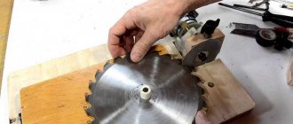
Quick change tool holder. We make an additional cassette.
In one of the previous reviews, eagle-eyed readers saw a quick-change toolholder on my lathe.
They asked him to look at it. I fulfill requests from workers ☺ Why do you need a quick-change tool holder? From the name it is obvious that for quickly changing cutters. Why is quick cutting tool change necessary? In turning, several dozen different cutters are used: passing, boring, scoring, threaded internal and external, grooving, cutting, etc. and so on. Some more often, some less often, but all are used.
A conventional tool holder can hold up to four cutters at a time, which is often sufficient for the production process. As a rule, the parts are of the same type and are sharpened on the production line. Having installed one set of cutters in the morning, you can work only with them until the evening.
When working individually or in home use, the cutters must be constantly changed. Unscrewing and tightening the screws, removing the cutter and selecting shims to adjust the height of the cutter is quite tedious. For these purposes, there is a quick-change tool holder with replaceable cartridges (cassettes).
I bought this tool holder quite a long time ago, exactly 5 years ago. So he went through fire, water and copper pipes. Has proven itself from the best side.
The tool holder is attached as follows: an axis is screwed into the upper support, onto which the tool holder is mounted. It is secured at the top with a nut. The kit included a plate that allows you to place it on the tool holder if you need to raise it higher.
I had a cylindrical bulge on the caliper, and I bored a hole in the plate to the diameter of the bulge.
The cartridge is fixed due to a movable wedge-shaped bar, which expands the dovetail groove. The fixation is simply tight.
Includes 5 cartridges
The first one is for ordinary rectangular holders. Groove height 13 mm, depth 8 mm. Four M6 screws secure the holder, one bolt with a wide washer and a lock nut allows you to control the height of the cartridge and cutter, respectively. The tip of the cutter should be at the height of the lathe spindle axis.
The second cartridge completely copies the first one with one addition: a V-shaped groove is milled on the lower flange of the holder mount, allowing you to mount rounded cutter holders.
The third cartridge is designed for attaching a cutting tool. And although high-speed steel cutters are becoming obsolete, this solution is very successful and in demand. The cutter can be sharpened without removing it from the cartridge. Cutting plate thickness 1.5mm (not included)
The fourth and most multifunctional cartridge combines rollers for rolling a notch onto the workpiece and a place for the cutter. I attach a small cutter to the cartridge for trimming workpieces.
Recommendations for use
The tool holder belongs to the main blocks of the machine and is fixed to it by means of a bolted connection.
The use of the device is especially effective when high-precision boring is required. Their design must be reliable and highly durable. It is equally important to install the cutter correctly, because the accuracy of metalworking noticeably decreases when even a small backlash appears. The tool holder on the lathe is used to attach the cutter vertically and horizontally. Inaccurate fixation in height is considered the main cause of defects and processing defects. When turning, the cutter must be placed so that its working part is on top of the centers of the machine. When boring, the cutter should be installed at the bottom of the centering plane.
The tool holder on the universal machine is placed on the upper slide of the support. There are also rotary and transverse devices located there, and the support itself is placed on the longitudinal slide of the frame. All these units together allow you to move the cutter in all directions and rotate it along the axis, which makes it possible to use the maximum number of metalworking operations.
The holder for a heavy type roughing machine is placed on an auxiliary slide. This is explained by the too large dimensions of the cross slide: moving them manually is extremely difficult.
Operation of metal cutting tools: important features
Let's look at the main points.
Rules for using metal cutting tools and useful tips
- Use metal cutting tools only for the work for which the devices are intended. Improper use may result in damage and breakage.
- Choose the most suitable cutting conditions. Do not exceed the limit parameters.
- Feed tools smoothly. Avoid jerking and sudden movements.
- Do not forget about the need to cool the instrument. Use the most suitable coolant for each application.
- Store tools in dry and heated areas. Individual tubes/containers are best suited for this. They reliably protect devices from mechanical damage and corrosion.
- Clean and degrease tools after each use. This is necessary for protection against corrosion.
- Follow safety regulations. Wear gloves. Wear a mask or safety glasses. To reduce noise levels, use earplugs or headphones.
Wear of metal cutting tools
During the operation of metal cutting tools, the characteristics of the devices deteriorate over time. Let's talk about types of wear and methods to reduce its level.
- Abrasive wear. Occurs when tools come into contact with workpieces. Particles of processed materials cause mechanical damage to the working surfaces of devices. The rate of abrasive wear decreases with increasing tool hardness. Carbide tools deteriorate much more slowly than their high-speed steel counterparts.
- Adhesive wear. The combined effects of friction and high temperatures lead to the formation of “setting bridges” on the working surfaces of devices. Chips moving during processing make the process of their formation and destruction cyclical. As a result, the contact surfaces of the working parts of the tools are gradually destroyed.
Image No. 2: adhesive wear of metal cutting tools
Note! The adhesive wear rate of tools made from high-speed steels and carbide models varies under different cutting conditions. Devices of the first category wear out faster at high temperatures, and the second - at low temperatures.
1. Diffusion wear. During contacts during cutting, the tool and processed materials mutually dissolve. Self-diffusion also occurs. As a result, areas of contact surfaces lose strength and become more brittle.
The graph below shows the dependencies:
- diffusion wear of carbide tools (curve 1) and devices made of high-speed steels (curve 2), depending on the cutting speed;
- hardness of workpieces on temperature during processing (curve 3).
Image No. 3: diffusion wear of metal cutting tools
2. Oxidative wear. On metal cutting tools, oxide films are dynamically formed and destroyed. The wear rate of the tool depends on their characteristics. When thin and durable coatings are formed, it decreases, and when thick and loose films appear, it increases.
3. Brittle fracture. This is the last of the main types of wear on metal cutting tools.
- Skol. A significant part of the working surface of the cutting tool is separated. Most often, chipping occurs due to the use of devices for a long time under high loads.
- Chipping. Small particles of steel are separated from the working surface. This is usually caused by the presence of small defects on the cutting edges.
Sharpening cutting tools for metal
Sharpening metal cutting tools is the main way to extend their service life. The operation consists of giving the working surfaces the required geometric parameters.
Photo No. 17: the process of sharpening a cutting tool
Sharpening is carried out once during the manufacture of the tool and periodically during operation. There are 2 main sharpening technologies.
1. Abrasive. It occurs with the use of abrasive wheels (electrocorundum and carborundum).
2. Non-abrasive. Three technologies are used.
- Analogous-mechanical sharpening.
- Electric contact sharpening.
- Chemical-mechanical sharpening.
After sharpening, finishing is carried out. This operation makes the parameters of the working parts of metal cutting tools ideal.
DIY holder design options
Despite the variety of designs, you can make a tool holder yourself from materials available in any garage or home workshop.
Homemade tool holders used for “garage” work are not subject to increased requirements for the accuracy of tool fastening, and you can save a significant amount for other needs. Video:
What tool holder is installed on your machine? Have you tried to make it yourself at home? Please share your opinion and experience in the comments.
Toolholders with a cylindrical shank with a diameter of 30 and 40 mm
Tool holders with a cylindrical shank for computer numerical control (CNC) machines are designed for securing prismatic cutters with a section
- 20x20 and 16x16 - for tool holders with a 30 mm shank,
- 25x25 and 20x20 - for tool holders with a 40 mm shank,
and also for securing tools with cylindrical and conical shanks. Upon customer request, they are equipped with adapter bushings with cylindrical and conical holes.
The tool holder shank complies with GOST 24900 and DIN 69880.
Radial toolholders
| Designation | d | D | L | H | H1 | H2 | B1 |
| 291.341.111 | 30 | 80 | 95 | 70 | 20 | 16 | 12 |
| 291.341.131* | 40 | 88 | 107 | 80 | 25 | 20 | 16 |
| Designation | d | D | L | H | H1 | H2 | B1 |
| 291.341.101 | 30 | 80 | 95 | 70 | 20 | 16 | 12 |
| 291.341.121* | 40 | 88 | 107 | 80 | 25 | 20 | 16 |
* - in versions of tool holders with a replaceable strip, the letter “A” is added to the tool holder designation code.
Axial tool holders
| Designation | d | D | L | H | H1 | H2 | B1 | B2 | A2 |
| 291.341.211 | 30 | 78 | 125 | 71 | 20 | 16 | 10 | — | — |
| 291.341.231* | 40 | 88 | 148 | 78 | 25 | 20 | 12,5 | 30 | 50 |
| Designation | d | D | L | H | H1 | H2 | B1 |
| 291.341.201 | 30 | 78 | 125 | 67 | 20 | 16 | 10 |
| 291.341.221* | 40 | 88 | 148 | 81 | 25 | 20 | 12,5 |
* - in versions of tool holders with a replaceable strip, the letter “A” is added to the tool holder designation code.
| Designation | d | D | L | H | B1 | N | d1 | d2 |
| 291.342.311 | 30 | 68 | 111 | 62 | 25 | 3 | 23,825 | 64 |
| 291.342.331 | 40 | 83 | 143 | 74 | 25 | 4 | 31,267 | 70 |
Tool holder for tools with cylindrical shank
| Designation | d | D | L | H | d1 | A |
| 291.342.200 | 30 | 84 | 111 | 62 | 25 | 45 |
| 291.342.222 | 40 | 116 | 123 | 75 | 32 | 65 |
| Designation | d | D | L | H | B1 | d1 | d2 | C |
| 291.342.112 | 30 | 68 | 121 | 66 | — | 32 | — | 54 |
| -01 | 30 | 68 | 121 | 66 | — | 25 | — | 54 |
| -02 | 30 | 68 | 126 | 66 | — | 20 | — | 59 |
| -03 | 30 | 68 | 130 | 66 | — | 16 | — | 63 |
| 291.342.132 | 40 | 83 | 138 | 74 | 55 | 32 | 70 | 63 |
| -01 | 40 | 83 | 138 | 74 | 55 | 25 | 70 | 63 |
| -02 | 40 | 83 | 138 | 74 | 55 | 20 | 70 | 63 |
| -03 | 40 | 83 | 138 | 74 | 55 | 16 | 70 | 53 |
Varieties and design features
There are actually a lot of machines and they perform all kinds of metal processing operations, but we will highlight the most famous types
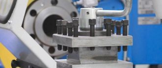
Multi-incisor
Designed for processing complex parts made from pipes, shaped profiles or rods of different sections. Multi-cutter or multi-spindle machines are mainly used in batch production.
Performed operations:
- drilling;
- thread;
- turning;
- pruning;
- boring;
- countersinking;
- deployment.
Multi-cutting machines have high productivity due to the large area of the drive mechanism, rigidity of the structure, and the ability to perform several operations simultaneously.
Carousel
A group of machines for working with large-sized parts and workpieces. The parts processed on them are short in length, but have significant weight and diameter.
Features of carousel models:
- used for processing conical or cylindrical surfaces;
- grooves of various configurations are made;
- You can also do grinding, milling, trimming ends;
- thread cutting.
In addition to the basic elements of any lathe, this type has additional equipment:
- table with faceplate;
- racks for moving the traverse.
Backing
The machines are designed for processing the back surfaces of tool teeth. It can also be used to perform other turning operations. The backing machine is distinguished by its special support design. The part is backed up as follows:
- rotational movement of the part;
- reciprocating movement of the cutting tool towards the part.
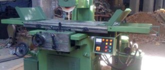
Screw-cutting
The most common group of machines. Widely used in serial and individual production. Screw-cutting models can be found in workshops, schools, and in any industry. They are easy to operate and maintain.
REFERENCE! The screw-cutting lathe is a universal model for all kinds of processing of metal workpieces. It can be used to make various types of threads: modular, inch, metric.
Structural elements:
- bed;
- front and rear stock;
- caliper;
- apron;
- gearbox.
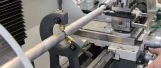
Revolver
Revolver group machines are designed for processing parts from calibrated rods. Operations that can be performed on this equipment:
- turning;
- boring;
- shaped turning;
- countersinking;
- drilling;
- thread formation;
- deployment.
REFERENCE! The name of the machines in this group comes from a special holder. It can be driven or static. The drive type gives more possibilities for carrying out various operations.
Universal
Universal lathes include screw-cutting machines, since they can perform almost any metal operation.
Main technical characteristics of the universal machine:
- rotation speed (number of revolutions); accuracy class; it is indicated in the product labeling with the letters S, B, N, A, P;
- number of gears;
- what sizes of parts can be installed;
- weight and dimensions of the machine;
- the amount of feed and maximum movement along the axis.
Purpose of the tailstock of turning equipment
The tailstock of a lathe, the design of which can include several design options, is necessary not only for fixing parts of considerable length, but also for fastening various tools: drills, taps, reamers, etc. An additional center of the machine, which is installed on the tailstock, can be rotating or stationary.
Tailstock structure: 1, 7 – handles; 2 – handwheel; 3 – eccentric; 4, 6, 9 – screws; 5 – traction; 8 – quill; A – counterbore
A scheme with a rotating rear center is used if the equipment is used for high-speed processing of parts, as well as when removing chips that have a large cross-section. When implementing this scheme, the tailstock is made with the following design: two bearings are installed in the quill hole - a front thrust bearing (with tapered rollers) and a rear radial one - as well as a bushing, the inner part of which is bored to a cone.
Axial loads arising during processing of a part are absorbed by a thrust ball bearing. Installation and fixation of the rear center of the equipment is ensured by the tapered hole of the bushing. If it is necessary to install a drill or other axial tool in such a center, the sleeve can be rigidly fixed with a stopper, which will prevent it from rotating with the tool.
Rotating center KM-2 of a table lathe Turner-250
The tailstock, the center of which does not rotate, is fixed to a plate that moves along the guides of the machine. The quill installed in such a headstock moves along the hole in it using a special nut. In the front part of the quill itself, into which the center of the machine or the shank of the axial tool is installed, a conical hole is made. The movement of the nut and, accordingly, the quill is ensured by the rotation of a special flywheel connected to the screw
What is important is that the quill can also move in the transverse direction; without such movement it is impossible to process parts with a flat cone
Step-by-step device assembly process
When all the necessary parts have been turned, it is necessary to assemble them into a single structure.
The parts of the future tabletop lathe are assembled on the assembly table.
It was decided to make the structure from flanges machined from round timber with a diameter of 120 mm. To make them easier, a central hole of Ø 55 mm is drilled in them. There are three holes Ø 20 mm.
Additional holes for threaded fasteners are drilled at the end. M6 screws can be used to secure the remaining parts in a given position.
A bronze bushing is pressed in for the future lead screw. Internal Ø 16 mm.
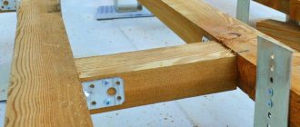
The bed guides are made of ductile cast iron. They have longitudinal grooves. The cylindrical part allows it to be fixed in the flange holes.
The guide is inserted so as to combine all the existing elements.
To maintain a given distance, spacer bushings are used. They are installed in the spacer between the flanges.
The second guide is made exactly the same as the first.
Having assembled the base for the headstock, proceed to assembling the rear one.
The frame is tightened with nuts. The foundation of the future bed has been created.
The machine will stand resting on the front supports. They are secured with screws to the flanges.
Support bushings move along the guides. The caliper and tailstock will be mounted on them. The long sleeve acts as a guide, and the short one acts as a support. The grooves on the rollers do not allow them to move.
Structurally, the support bushings are made of different lengths. This solution allows you to increase the working stroke.
The length of the processed parts can be sufficient so that the parts have dimensions up to 250 mm.
The caliper platform is secured with M6 screws.
The holes for the platform are drilled in place. This part is made individually. If you try to make it only according to the drawing, a jamming effect may appear.
By analogy, the tailstock platform is made. It is also drilled in place. It is necessary to ensure sliding movement along the guides.
It is necessary to ensure the rigidity of the frame. A special cylindrical half ring is machined for the headstock. It is bolted to the flanges.
The movement of tools on the support or tailstock is carried out by a lead screw. A rectangular thread with a slight slope (12.5 ⁰) is machined on it. When the lead screw rotates, the parts attached to it move forward or backward. Depends on the direction of rotation.
A hole with a pressed bushing was created for the lead screw.
To ensure that the screw rotates freely, but does not itself move along its axis, thrust bearings are used. They are placed in front and behind the rear support.
To prevent axial movement of the lead screw, a locking sleeve is installed. It is secured with an M6 bolt. Now the screw will not move along the axis, but it can rotate.
A vernier (a device with notches) is placed on top of the fixing sleeve. One turn of the screw moves the caliper or tailstock 10mm. Using the scale as a guide, precise displacements can be made in the longitudinal direction.
To rotate the lead screw, a handwheel is installed. The small handle allows you to easily rotate the flywheel.
Risk helps you navigate. Looking at it, the desired axial displacement is set.
The machine bed is assembled. Now you need to install the headstock. The part will be recorded in it.
Transverse movement guides are installed on the plates.
The headstock is mounted on top. The picture shows a pulley block, a three-jaw chuck and a central bushing.
The pulleys can be easily removed and installed on the spindle.
The spindle itself is installed inside the central bushing.
There are radial bearings between the spindle and the bushing. They allow free rotation.
The central bushing is bolted to the frame.
After installing the bearings, a spindle with a three-jaw chuck is mounted. A hole Ø 35 mm is machined inside the spindle. If necessary, workpieces of smaller diameter can pass through it.
The machine is ready. The drive is carried out through V-belts from an electric motor installed to the side.
Video: DIY mini lathe.
Installing the cutter in the tool holder
The cutter is installed in the cutter holder so that its top is located at the level of the center axis (Fig. 16). The installation of the cutter is controlled at the rear center. Pads made of mild steel are placed under the cutter holder, and the number of pads should be minimal, and the cutter holder should rest on the pads of the entire surface. The protrusion of the cutter from the tool holder should not exceed one and a half heights of the holder, i.e. l 0, cut off the part with cutting cutter IV. Then the cut-off part is again secured in the chuck by the surface Æ25, the second end is trimmed and chamfered with cutter I.
Thus, the operation of turning the workpiece of the “Finger” part was performed in two setups, with five transitions performed during the first setup, and two transitions during the second setup.
Rice. 15 — Drawing of the “finger” part
Rice. 16 - Technological process for manufacturing the “Finger” part in one operation: a – technological process diagram; b – tool holder adjustment diagram;
1-6 – transitions; incisors: I – bent through passage, II – persistent through passage;
III – groove, IV – cutting
Contents of the report
1. Draw up a sketch of the layout of a 1K screw-cutting lathe, indicating the purpose of its main parts.
2. Describe the main and auxiliary movements of the working parts of the machine, methods for setting machine modes and the mechanism for their implementation.
3. Complete a sketch of the part (issued by the supervisor).
4. Draw a sketch of the installation of the workpiece on the machine.
5. Describe the types of work performed on the machine and indicate which of them will be used when processing the part.
6. Draw up a technical process for processing a part, indicating sketches of transitions and tools.
7. Outline the classification of cutters and indicate which of them are used when processing the part.
1. Explain the essence of turning.
2. Name the main parts of a screw-cutting lathe and their purpose.
3. List the cutting modes, the main and auxiliary movements of the working parts of the machine, methods for their installation and activation.
4. Tell us about the types of work performed on lathes
5. Tell us about the design and types of turning tools.
6. How the workpiece is secured on lathes.
7. What is the technological process and what elements does it consist of?
1. Design of metal-cutting machines and machine systems. Reference book. – M.: Publishing house. MSTU im. Bauman. 2000.
2. T.I. Tishchenina, B.V. Fedorov. "Lathes and working on them." -M.: Mechanical engineering. 1990.
3. Technology of structural materials. Under general ed. A.M. Dalsky. — M.: Mechanical Engineering. 1992.
Volume 0.7 conventional p.p., 0.6 academic sheets Offset. Format 60x84/16
Paper type N 3. Order No. 521. Circulation 180. Price.
Address of the university and printing enterprise:
344010, Rostov-on-Don, pl. Gagarina, 1.
source
Tool holders for metal lathes: drawing, design, GOST
The tool holder serves to secure the cutters on the support of the lathe, and as a result, it moves in the transverse and longitudinal directions relative to the workpiece. Another name for this device is a cutting head.
They are divided into two-position and four-position, i.e. in the first version, two cutters can be screwed into the tool holder at the same time, in the second – four. This allows you to quickly change tools while working by rotating the cutting head to a different position with the desired cutter.
Four position cutting head
To quickly change tools, cartridge-type tool holders are used, which can be installed on almost all types of lathes. Replacement cartridges are manufactured for cutters with tetrahedral and round holders.
Quick change tool holder
DIY tool holder (holder)
If desired or necessary, the tool holder can be made independently. Workpiece material – steel 45.
Another video on remaking the holder