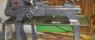
Vertical lathe 1512
On sale you can find a relatively small number of machines that can be used for processing large parts. Among all the models created at the time of the existence of the USSR, we note the 1512 rotary lathe. Its purpose is to process parts of medium and large sizes. Due to its high reliability and practicality in use, this model became the basis for the creation of various modifications and was actively imported to various countries around the world. The technical characteristics of the 1512 rotary lathe determine its applicability in mechanical engineering, shipbuilding or other production. When installing additional equipment, the purpose of the 1512 vertical turning lathe is significantly expanded; it can be used to carry out more than 10 types of processing of workpieces made of various alloys. The scope of application of the model 1512 is very extensive. As a rule, it is installed in the case of medium-scale and piece production of various parts. This is due to the fact that in the case of turning large workpieces, a large layer of material is removed. Even when using a cutting tool made of wear-resistant material, a layer can be removed in one pass, provided that the maximum force should not exceed 35 kN. The main operations that can be carried out on this equipment: Processing of conical and cylindrical surfaces. Performing boring operations. Passing a cutting tool along a flat surface, which is an end. Carrying out work on creating holes and boring them. The model has been produced since 1935 by the Krasnodar Sedina plant. After using this model for a long time, a fairly large number of different modifications appeared, which also became popular.
Old Soviet models of wood and metal machines
Edge bending machines: types, description, principle of operation
Soviet equipment is still in use in production. Some people fundamentally prefer to equip their home workshops with units from the USSR.
Important!
It is sometimes difficult to find equipment or components for Soviet equipment in case of breakdown.
Screw-cutting lathe IT-1M
The lightweight machine was intended for gaining practice in workshops. Allows you to process cylindrical workpieces from the outside, drill and boring, and cut threads. Currently out of production.
Screw-cutting lathe TV-6
Appeared on the market in the 80s. It is mainly used for training future turners in workshops and training centers. Allows you to perform basic operations.
Characteristics:
- Spindle diameter - 12 mm.
- Spindle speed - 130-170 rpm.
- The distance between centers is 350 mm.
- The maximum processing length is 300 mm.
Lathes Universal 2 and Universal 3
Tabletop machines for the production of small parts. Most turning jobs are possible. The maximum diameter and length of the workpiece is 12.5 cm and 18 cm.
Lathe TSH-3
Performs the function of a sharpening and grinding unit. Suitable for use in home workshop and industrial purposes. In addition to classical turning work, the unit is suitable for finishing grinding of products and sharpening cutting and metalworking tools.
1E61M, 1E61PM, 1E61VM screw-cutting lathes
Refers to special machines that provide higher processing accuracy. All three modifications belong to the turning-screw-cutting group with a height above the centers of 175 mm.
The diameter of the processed rod does not exceed 32 mm. The maximum movement distance of the caliper is 200 mm.
Screw-cutting lathe 1М63Н
Multifunctional unit designed to perform all types of turning operations. This model also allows you to work with conical surfaces and cut multi-start threads.
The letter H in the marking indicates the ability to obtain dimensions of normal accuracy. It is possible to install additional equipment when working with large-sized workpieces.
Turret lathe 1341
The turret group machine allows processing using several tools at the same time. Available operations:
- Treatment of external and internal surfaces.
- Thread cutting.
- Drilling, countersinking, reaming.
- Working with shaped surfaces.
Processing is performed in automatic and semi-automatic mode. It is possible to produce parts from rods and piece blanks.
Screw-cutting lathe 1N65
An improved modification of the 1M65 unit. It is possible to process cylindrical and conical parts, as well as complex shaped surfaces.
Specifications:
- The height of the center above the bed and support is 500 and 325 mm.
- Spindle diameter - 128 mm.
- The maximum weight of the workpiece is 5 tons.
- The maximum diameter of the workpiece in the jaws is 870 mm.
Screw-cutting lathe 1M63
Developed in the 50s for processing workpieces made of various metals. At that time, it was a unit with unique characteristics, and it was purchased by large industrial enterprises. It ensured high quality and precision processing when turning products of any complexity.
Screw-cutting lathe 1A616
The unit was produced in the 50s of the last century. In that era, the technical characteristics were among the best. The machine is successfully used in many enterprises to this day.
The equipment is designed for a wide range of work with small workpieces. The letter A indicates particularly high processing accuracy. It is possible to cut modular, inch, and pitch threads without restructuring the kinematics.
School lathe TV-4
Developed for teaching turning in school workshops and training centers. A universal machine suitable for basic turning operations. It is lightweight and small in size, which is why it is popular in home workshops.
Metal lathe Shkolnik TV-7
The machine is manually controlled, designed for processing workpieces 100-300 mm. Supports four speed modes. Allows you to perform basic operations - external turning, boring, cutting metric threads, end processing, drilling holes. Purpose - practical training of future turners.
Tabletop metal lathe TV-16
A machine with small dimensions for performing operations of medium complexity. Available for hole drilling, thread cutting, external turning, boring.
Options:
- The distance between centers is 250 mm.
- The maximum diameter of the workpiece above the bed is 160 mm.
- The spindle hole diameter is 18 mm.
- Power - 0.4-0.5 kW.
Models of milling machines
Domestic metal-cutting machines, depending on the type of processing, are divided into nine groups. In turn, each group is divided into nine subgroups representing machines according to their types. Milling machines belong to the sixth group. The classification of milling machines by type is given in table. II.1.
The designation (encryption) of milling machine models is carried out according to the following rules:
- the first digit indicates the group;
- the second - determines the type of machine;
- the third and fourth symbolize its size.
In addition to numbers, the designation may contain capital letters. If there is a letter between the first and second digits, this means that the machine has been improved compared to the previous model. The alphabetical sequence of these letters indicates further improvements. Thus, the horizontal milling cantilever machine model 6T82 is newer than the machine model 6P82. The letters at the end of the cipher indicate: P - increased accuracy; G - change in the basic model; Ш - wide versatility; C — presence of cyclic program control.
Models of milling machines with computer numerical control (CNC) at the end of the code have the letter F and numbers next to it:
- 1 - for machines with digital display 1 and preset 2;
- 2 - for machines with a CNC positioning system;
- 3 - for machines with a contour (continuous) system;
- 4 - for multi-operational machines with a contour (or mixed contour and positional) CNC system and automatic tool change from the tool magazine.
The dimensions (mm) of the machine table are taken as a sign of dimensional characteristics. According to this feature, the machines have five gradations:
| Size | 0 | Square | table | 200x800 |
| >> | 1 | >> | >> | 250x1000 |
| >> | 2 | >> | >> | 320x1250 |
| >> | 3 | >> | >> | 400x1600 |
| >> | 4 | >> | >> | 500x2000 |
Table II.1 Classification of milling machines by type
| Subgroup of machines of the sixth group | ||||||||
| 1 | 2 | 3 | 4 | 5 | 6 | 7 | 8 | 9 |
| Machine type | ||||||||
| Vertical milling console | Continuous milling machines | Free subgroup | Copying and engraving-milling machines | Vertical non-cantilever | Longitudinal milling | Console wide-universal | Horizontal console | Different |
The most common types of milling machines are horizontal, universal and vertical. In table II.2 and II.3 their technical characteristics are given.
Horizontal cantilever milling machines have a horizontally located spindle that does not change its location. The stand can move perpendicular to the spindle axis in the horizontal and vertical directions and along an axis parallel to it.
- Universal cantilever milling machines differ from horizontal ones in that they have a table that can be rotated to the required angle.
- Vertical cantilever milling machines have a vertically located spindle that moves vertically and, in some models, rotates. The table can move in a horizontal direction perpendicular to the spindle axis and in a vertical direction.
- Widely universal cantilever milling machines, unlike universal ones, have, in addition to the main horizontal spindle, an attached head with a spindle that rotates around the vertical and horizontal axes.
- Consoleless milling machines have a spindle located vertically and moving in this direction. The table moves only in the longitudinal and transverse directions.
- Longitudinal milling machines have a table that can only move in the longitudinal direction along the guide surfaces of the bed. Vertical and transverse movements are obtained by spindle heads and spindles. The machines can have up to two vertical and up to two horizontal spindles in single- and double-column versions.
- Based on the principle of operation, volumetric milling flocks are divided into direct and servo copying machines, carried out by feeling the model with a copying finger, as well as program-controlled machines that operate simultaneously and continuously along three mutually perpendicular coordinates.
- Continuous milling machines (rotary milling machines) have a vertically located spindle (spindles) that move vertically and a round table that can continuously rotate at the working feed rate. Multi-position workpiece clamping and processing. An example of such machines is the model 6A23 machine with a table diameter of 1400 mm.
- Key-type milling machines (of the “miscellaneous” type) have a vertical spindle that carries out rotational and, at the same time, planetary motion. The diameter of the planetary movement can be changed according to the specified width of the keyway. The table moves back and forth in the longitudinal direction. The work cycle is automated. Examples of these machines can be machines of models 6D91, 6D92, etc.
Table II.2. Technical characteristics of cantilever and non-cantilever vertical milling machines
| Parameter | Vertical milling machines | |||||||||
| console | non-console | |||||||||
| Model | ||||||||||
| 6T11 | 6Р11Ф3 | 6T12 | 6P13 | 6Р13Ф3 | 6520F3 | 6550C | 6550MF3 | 6560TS | 6560MF3 | |
| Dimensions of the working surface of the table, mm | 250x 1000 | 250x 1000 | 320x 1250 | 400x 1600 | 400x 1600 | 250x 630 | 500x 1250 | 500x 1250 | 630x 1600 | 630x 1600 |
| Maximum movement, mm: | ||||||||||
| longitudinal | 560 | 630 | 700 | 1000 | 1000 | 500 | 1000 | 1000 | 1250 | 1250 |
| transverse | 190 | 300 | 240 | 320 | 400 | 250 | 500 | 500 | 630 | 630 |
| vertical (consoles and headstocks) | 340 | 120 | 420 | 420 | 150 | 275 | 530 | 530 | 625 | 625 |
| Distance from the end of the spindle to the table, mm: | ||||||||||
| greatest | 380 | 380 | 450 | 500 | 450 | — | 630 | 630 | 900 | 900 |
| least | 30 | 30 | 30 | 30 | 70 | — | 100 | 100 | 125 | 125 |
| Inner spindle taper (7 :4)* | 40 | 40 | 45 | 45 | 45 | 45 | 50 | 50 | 50 | 50 |
| Spindle speed, rpm | 65- 1800 | 40- 2000 | 32- 1600 | 31.5- 1600 | 40-2000 | 31.5- 1600 | 31.5- 1600 | 31,5-1600 | 25- 1250 | 5.6-2000 |
| Number of controlled coordinates | — | 3 | — | — | 3 | 3 | 3 | 3 | 3 | 3 |
| Feed drive type | — | Step follower | — | — | Step follower | Step follower | — | — | — | Step follower |
| Feed speed, mm/min: | ||||||||||
| longitudinal | 35-980 | — | 25-1250 | 25-1250 | — | — | 10-2000 | — | 10-2200 | 0.1 — 4800 |
| transverse | 25-760 | — | 25-1250 | 25-1250 | — | — | 10-2000 | — | 10-2200 | Stepless |
| vertical | 12-380 | — | 8.3-416 | 8.3-416 | — | — | 4-800 | — | 3-730 | |
| Rapid movement speed, mm/min: | ||||||||||
| longitudinal | 2900 | 2400 | 3000 | 3000 | 2400 | 1200 | 3000 | 3000 | 3000 | 9600 |
| transverse | 2300 | 2400 | 3000 | 3000 | 2400 | 1200 | 3000 | 3000 | 3000 | 9600 |
| vertical | 1150 | 2400 | 1000 | 1000 | 2400 | 1200 | 800 | 800 | 1000 | 9600 |
| Electric motor power, kW: | ||||||||||
| main drive | 4,5 | 5.5 | 7 | 10 | 7,5 | 4 | 10 | 10 | 13 | 11 |
| feed drive | 1.7 | — | 1,7 | 3 | — | — | 2,2 | — | 5.5x2 | — |
| Designation of the spindle end cone according to GOST 24644 -81 | ||||||||||
Table II.3. Technical characteristics of cantilever horizontal and universal milling machines
| Parameter | Horizontal milling | Universal milling | ||||||
| Model | ||||||||
| 6T80T | T811 | 6T82G | 6T83G | 6676F2 | 6Р81Ш | 6Т82Ш | 6Т83Ш | |
| Table working surface size, mm | 200x801 | 250x1000 | 320x1250 | 400x1600 | 250x630 | 250x100С | 120x1250 | 100x1600 |
| Maximum movement, mm: | ||||||||
| longitudinal | 500 | 560 | 700 | 1000 | 400 | 560 | 800 | 1000 |
| transverse | 160 | 190 | 240 | 320 | 250 | 190 | 250 | 320 |
| vertical | 350 | 350 | 420 | 420 | 400 | 350 | 470 | 350 |
| Distance from spindle axis to table, mm: | ||||||||
| least | 40 | 30 | 30 | 30 | 95 | 30 | 40 | 30 |
| greatest | 360 | 380 | 410 | 450 | 545 | 340 | 300 | 380 |
| Inner spindle taper (7:24) | 40 | 40 | 45 | 45 | 40 | 40 | 45 | 45 |
| Spindle speed, rpm | 50-2240 | 65-1800 | 32-1600 | 31.5 -1600 | 40-2000 | 65-1800 | 31.5-1600 | 31.5-1600 |
| Table feed speed, mm/mm: | ||||||||
| longitudinal | 25-1120 | 35-980 | 25-1250 | 25-1250 | 2.5-1600 | 35-980 | 25-1250 | 25-1250 |
| transverse | 18-800 | 25-760 | 25-1250 | 25-1250 | 2.5-1600 | 25-760 | 25-1250 | 25-1250 |
| vertical | 9-400 | 12-380 | 8.3-416 | 8.3-416 | 2.5-1600 | 12-380 | 8,3-416 | 8,3-416 |
| speed of rapid table movement, mm/min: | ||||||||
| longitudinal | 2300 | 2900 | 3000 | 3000 | 3000 | 2900 | 3000 | 3000 |
| transverse | 1600 | 2300 | 3000 | 3000 | 3000 | 2300 | 3000 | 3000 |
| vertical | 800 | 115, | 1000 | 1000 | 3000 | 1150 | 1000 | 1000 |
| Electric motor power, kW: | ||||||||
| main drive | 2,8 | 4,5 | 7 | 10 | 2,2 | 4,5 | 7,5 | 10 |
| feed drive | — | 1,7 | 1,7 | 3 | 0,75 | 1,7 | 2,2 | 3 |
| Number of controlled coordinates | — | — | — | — | 3 | — | — | — |
| Feed drive type | — | — | — | — | Step follower | — | — | — |
| *Designation of the spindle end cone according to GOST 24644-81 | ||||||||
Safety regulations
Turning and milling machining centers for metal
When working even on the simplest school unit of a turning group, it is necessary to strictly observe the safety requirements, which are as follows.
- All operator clothing must be fastened with all buttons.
- Before starting work, it is necessary to perform a technical inspection of the device, during which individual malfunctions in its operation may be identified. If such malfunctions are detected, if the operator cannot quickly eliminate them with his own hands, it is necessary to call a technician (or an adjuster) who will deal with this issue.
- All technological operations on a lathe should be carried out only in accordance with the technical specifications, for which you must first obtain a drawing or a detailed technological processing process from the master.
Safety Reminder when working on lathes (click to enlarge)
The operator of a machine, including one equipped with a CNC system, is strictly prohibited from:
- start work if the device is currently being adjusted or serviced;
- work on the machine if its centers have undergone significant wear;
- use tools and clamping elements during processing that show even the slightest signs of malfunction;
- independently troubleshoot problems related to the electrical system of the equipment;
- move away from the machine, which is turned on, and also entrust its control to unauthorized persons.
From soft to hard
Machines and equipment
We are on the territory of the Kolomna Heavy Machine Tool Plant, which turned 100 years old this year. In the Russian Empire, they started here with horse-drawn carts, then, in Soviet times, they made cannons and, finally, they moved on to machine tools. ZTS was a real giant of Soviet industry and occupied a vast territory, which is now divided between several legal entities. In general, what usually happened with this kind of enterprise in the years when the country was carried away by trade and finance happened: the plant went bankrupt. It turned out that Russian machines were not needed only by the Japanese. And yet, the centenary of the famous plant did not become a mourning date. Slowly, step by step, here in Kolomna, as well as in Sterlitamak, Ivanovo and other cities, the Russian machine tool industry is being born again.
And here's what's interesting. The people who stood at the origins of the new life of the famous Kolomna plant did not at all come from heavy industry. They came from the very “knowledge economy”. Back in 1995, a group of students, graduate students and graduates of the Moscow “Stankin” united into a production team and began to fulfill orders from Western machine tool companies to develop software for automated control systems. There was no talk of any “heavy metal” - it was an era when programmers and “computer scientists” in general were the heroes of the day. Gradually, the scope of activity and the circle of partners of the team - now it became known as ZAO Stankotech - expanded. There was an interest not only in creating software for machine tools, but also in their modernization and re-equipment based on modern CNC tools. Finally, in 2011, ZAO Stankotech came to Kolomna. The company absorbed the bankrupt enterprise SKB-ZTS LLC, created on the basis of the precision machine shop of the former Kolomna Heavy Engineering Plant. In these areas with a glorious history, the “machine technicians” began to create a new enterprise, which now not only modernizes old machines, but also produces new ones. In 2013, ZAO Stankotech, which manages production in Kolomna, merged with the machine tool plant in Sterlitamak (NPO Stankostroenie) into the STAN group. In October of this year, it was announced that two more machine-tool production facilities would join the group in Ryazan and Ivanovo.
Technologies Surgical operations “remotely”: is it possible?
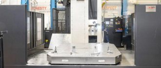
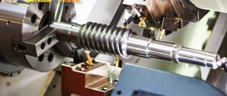
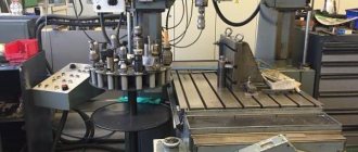
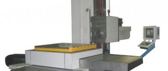
Flexibility and precision In the photo, the pipe bending machine performs its slow but very delicate work. Under computer control, it creates complex three-dimensional configurations from pipes - such parts are used, in particular, in rocket fuel systems. Another new product of Stankotech JSC, located on the factory floor, is the OCP 300 model machining center, which is designed for processing large-sized parts (plates, frames, housings) made of light metal alloys and composite materials. The machine can process parts of any geometric shape from five sides without reinstallation.
The machines that are being built and will be built today in Kolomna are not ordinary equipment at all. A unique pipe bending machine has been manufactured and is operating in the workshop, a universal rolling mill URS-3200 is being gradually implemented in metal, and a machine for cutting out wafer backgrounds is being designed. No, confectionery products have nothing to do with it, and just listing the names of these machines is enough for an experienced person to understand which industry needed the latest Russian machines. But first, let’s talk about the Japanese.
Where can I buy equipment from those times?
The seller delivers and, if necessary, advises on upgrading the equipment. The main advantage of Soviet equipment is that it can be easily improved, and all main components can be easily replaced, which significantly extends the service life of the machine.
Soviet-made machines are distinguished by reliability and quality of processing, as well as versatility. Most models can be further improved and their functionality expanded. That is why almost all Soviet machines are still used in mechanical engineering and metalworking production.
The most reliable and best models for metal and wood processing
Of the variety of Soviet equipment, there are several models that are considered the best and have been used for many decades, including in modern production.
Vertical milling 6P12
This machine is widely used in the engineering industry. Used in medium-scale production and when processing small workpieces. The main advantage of this equipment is its simplicity and reliability. This equipment can be used to process workpieces made of steel, cast iron, as well as difficult-to-cut metals.
At the moment, the Gorky plant no longer produces these machines, but they are popular and are still used in production. The equipment allows you to work with rounded and uneven surfaces.
NGF 110 Ш4
This is a tabletop machine that is still used as special school equipment to this day. Designed for milling work on horizontal surfaces, grooves, and other planes. The equipment uses disk, end and face mills, as well as shaped cutters. The cutters are mounted on the mandrel using mounting rings and a nut.
This is a highly versatile machine with a high class of accuracy for processing parts. Equipped with horizontal and vertical spindles, it is capable of performing a range of milling and boring operations. The presence of two spindles, one of which is rotary, makes the device indispensable in the field of mechanical engineering, in the production of tools, relief stamps and other devices. The machine is used in single and small-scale production and is used in tool and mechanical shops of machine-building enterprises.
OF 55
Another option for highly versatile milling equipment with a higher accuracy class. The machine is equipped with two mechanical feeds and one additional manual feed. has two spindles in its design: vertical and horizontal. Rotating vertical spindle, can be rotated at any angle.
This equipment can be used to perform: drilling, reaming, chiselling, centering, countersinking, reaming. The main advantage of the machine is a wide range of spindle speeds and feeds. This enables cost-effective processing of a wide variety of parts in energy-efficient modes.
Vertical milling 6T13
This is a cantilever vertical milling machine, produced by the Gorky Milling Machine Plant and is still considered one of the best units for processing vertical and horizontal planes, grooves, corners, frames, and gears. The machine has 3 operating modes: automatic, manual and jog.
Rectangular guides of the frame and console give the equipment additional rigidity. It is possible to expand the technical parameters of the machine through modernization. A big plus is the mechanized fastening of the tool.
Vertical milling 6Р13
Another model produced by the Gorky Milling Machine Plant. Equipped with a vertical quill spindle. The table moves crosswise in a horizontal plane. Designed for processing parts made of steel, cast iron, hard-working surfaces, as well as non-ferrous metals. Processes vertical, horizontal and inclined planes, corners, grooves, frames and various curved surfaces. It is successfully used for processing cabinet workpieces of various shapes and sizes.
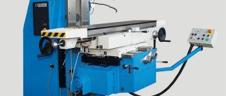
Horizontal milling 6Р82
The horizontal cantilever milling machine performs high-precision work on a variety of types of metal. Despite the fact that the equipment is over 40 years old, the machine is still considered one of the most affordable and reliable units for various branches of mechanical engineering. The role of the console is performed by special brackets. The spindle in this unit always remains in the same position. The work table itself can be installed at right angles to the spindle.
Application area
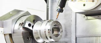
Lathes are used for internal and external machining of cylindrical surfaces. Shafts, bushings, flanges, pulleys, couplings and other parts can be manufactured.
The workpiece is installed in a chuck, which rotates together with the spindle at specified speeds. The cutting tool makes a translational movement. Due to this, the workpiece acquires the desired shape and size.
Types of operations:
- End processing.
- Grinding the outer surface to a given diameter.
- Drilling and boring holes.
- Grooving.
- Cutting internal and external threads.
- Reaming and countersinking.
Scope of application of lathes
The purpose of creating equipment is to process various parts on a metal and wooden base. To do this, various operations are performed:
Turning cutters boast the widest functionality if you have the necessary tools and equipment:
- Drilling.
- Trimming, end processing.
- Thread cutting.
- Internal surface treatment.
- Turning grooves, cones and other similar shapes.
- Boring, turning surfaces in the form of cones, cylinders, smooth shaped type.
The machines can be used in both large-scale and small-scale production. Each owner chooses the option that suits him. The choice of models was wide from the very beginning.
Lathe design
The main nodes are:
- The bed is a supporting structure on which all components are located.
- Headstock - it contains the spindle, which rotates with the part, and the gearbox.
- Tailstock - additionally secures the part during processing in the centers. The quill is used to attach a cutting tool (drill, reamer).
- Caliper - carries a tool holder into which turning tools are attached. Moves in the transverse and longitudinal direction at a given speed.
- Feed box - provides movement from the lead screw or shaft to the caliper.
Important! On most models, the main components are unified.
Milling machines: general information, classification, designation
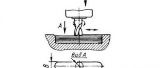
Milling machines are designed for processing external and internal flat, shaped surfaces, shoulders, grooves, straight and helical grooves, splines on shafts, cutting gears, etc.
The designs of milling machines are varied. In general, milling machines can be divided into two main groups:
- general purpose or universal milling machines (vertical milling, horizontal milling, longitudinal milling
- specialized and special milling machines (slot milling, key-milling, rotary milling, copy milling, etc.)
The main shaping movements of milling machines are the rotation of the cutter (the main movement) and the feed movement, which is imparted to the workpiece or cutter.
The main movement and feed drives are operated separately. Auxiliary movements associated with the supply and removal of the workpiece to the tool are mechanized and carried out by a drive of accelerated movements.
The main elements of machine mechanisms are unified.
The main parameter characterizing general-purpose milling machines is the size of the working surface of the table.
Based on their design features, these machines are divided into:
- console machines (the table is located on a lifting console bracket)
- non-cantilever machines (the table is moved on a fixed frame in the longitudinal and transverse directions)
- continuous machines (rotary and drum)
- a — universal console horizontal milling machine
- b - universal cantilever horizontal milling machine
- c — universal universal non-cantilever milling machine
- g — cantilever vertical milling machine
- d - non-cantilever vertical milling machine
- e - non-cantilever horizontal milling machine
- g - longitudinal milling machine
- h — rotary milling machine
- and - drum milling machine
Cantilever milling machines are most common in single, small- and medium-scale production of rice. 119, a, b, c, d). Horizontal and vertical cantilever milling machines are the most common type of machines used for milling work. Cantilever milling machines get their name from the cantilever bracket (console), which moves along the vertical guides of the machine bed and serves as a support for the horizontal movements of the table.
A universal cantilever milling machine (Fig. 119, a) has a horizontal spindle 2 and a retractable trunk 1, on which a shackle 3 is installed, supporting a mandrel with a cutter; the console 4 moves vertically along the guide of the rack 5. The console contains a slide 6 and a rotary table 7 .
Horizontal cantilever milling machines (Fig. 119, a) have a horizontally located spindle 2 that does not change its location. The table can move perpendicular to the spindle axis in the horizontal and vertical directions. Unlike the Universal console milling machine, the work table does not rotate around a vertical axis.
The wide-universal cantilever milling machine (Fig. 119; b, c) in addition to the horizontal spindle, has a spindle head 1, which can be rotated on the trunk in two mutually perpendicular directions, due to which the spindle with the cutter can be installed at any angle to the table plane and to the workpiece . An overhead head 2 is mounted on head 1, intended for drilling, reaming, countersinking, boring and milling.
A vertical cantilever milling machine (Fig. 119, d) has a vertical spindle 3, which is located in a rotating spindle head 2 mounted on a stand 1.
Cantilever-free vertical milling machines (Fig. 119, e), used for processing blanks of large parts, have a slide 2 and a table 3, which move along the guides of the frame 1. The spindle head 5 moves vertically along the guides of the rack 6. The spindle 4 has vertical axial movements when installing the cutter. The table moves only in the longitudinal and transverse directions.
Cantileverless horizontal milling machines (Fig. 119, e), used for processing blanks of large-sized parts, have a slide 2 and a table 3, which move along the guides of the frame 1. The spindle head 5 moves vertically along the guides of the rack 6. The spindle 4 has axial movements at installing the cutter.
Longitudinal milling machines (Fig. 119, g) are designed for processing blanks of large-sized parts. On the frame 1, two vertical posts 6 are installed, connected by a cross member 7. Milling heads 3 with horizontal spindles and a traverse (cross member) 4 are mounted on the guide posts. Milling heads 5 with vertical spindles are mounted on the latter. Table 2 moves along the guides of racks 4.
Rotary milling machines (Fig. 119, h), designed for processing surfaces with end mills, have one or more spindles 3 for finishing and roughing. The spindle head 2 moves along the guides of the rack 1. The table 4, rotating continuously, imparts feed rotation to the workpieces installed on it. The table with slide 5 has an installation movement along the guides of the frame 6.
Drum milling machines (Fig. 119, i) are used in large-scale and mass production. The workpieces are installed on a rotating drum 2, which has a feed movement. Milling heads 3 (for roughing) and 1 (for finishing) move along the guides of the racks 4.
Design of a lathe and photos of its individual parts
The design of this type of equipment always contains the following components:
- Electrical part. We are talking about electric drive motors. Power varies from model to model. The group also includes elements responsible for controlling certain parts of the machine. The main thing is that these parts meet safety requirements.
- Gearbox. In the presence of such a structural element, the machine support receives the energy of movement. Lead screws and rollers act as sources of this energy.
- Caliper. Fastens the cutting elements of the structure. Provides transverse and longitudinal feeding of devices. The design is necessarily complemented by the so-called bottom carriage, or several. Holders for turning tools are fixed on other carriages, at the top.
- The spindle head contains the spindle itself. In the inner part there is a gearbox. Woodworking machines are also not devoid of this part.
- Apron. Helps ensure that the movement of the roller is converted into movement of the caliper. The lead screw can also participate in this process.
- Bed. Refers to the load-bearing elements of turning units. Other elements of the machine are mounted on it.
The rest of the elements are supported by two special cabinets included in the set. They have a load-bearing function for equipment. Thanks to this part, the operator is able to select the maximum workpiece height that is most convenient. The cabinets are known for their massive construction.
USSR lathe
During the Five-Year Plans, during the Great Patriotic War and after it, the Soviet Union actively used various machines to boost the country's economy. In the USSR, lathes for metal and wood were most often used to create weapons, military equipment, as well as other devices and devices that would help in difficult times.
During the war, people actively worked on machines. The lathes of the USSR are well preserved, there are no photos left from those times, but the machines have survived to this day. And when you come to the museum of military equipment, most likely you will see devices from factories there. The machines were made well and with high quality, so that they would not wear out and would last for a very long time, and so it turned out.
Lathes in the USSR: which ones were used during the Union?
USSR lathes are still used in enterprises. New equipment is almost impossible to find. But the old one has retained all its characteristics; it is enough to replace some components to get the result.
Since the 18th century, special machines began to be used instead of manual labor. At first the designs were steam-powered, then they switched to using electric energy; there was no exception for USSR lathes. They have become one of the most important inventions that make modern life easier.
Safety rules when working on a lathe
The provisions of the safety rules are as follows:
- Compliance with the original technical specifications is mandatory when performing work. To do this, first obtain a drawing from the master. Or another type of description of the technological process associated with processing.
- Before starting work, be sure to conduct a technical inspection. This is necessary in order to detect and eliminate individual technical faults in a timely manner. If necessary, call a technician.
- Special clothes are fastened with all buttons.
https://youtube.com/watch?v=x1KTQFhY0YQ
Work cannot be started if any equipment adjustment or other types of maintenance are being carried out. Do not use machines whose centers are heavily worn. The same applies to any tools or clamping materials - you should discard them at the slightest sign of malfunction.
If the breakdown is related to the electrical part, the technicians are prohibited from fixing it themselves.
What are lathes used for?
This machine is needed to process parts (or their blanks) made of metals and wood by cutting or turning. Using a lathe, smooth cylindrical, shaped and conical surfaces of this shape are turned and bored, grooves (recesses on the product), cones are turned, internal surfaces are processed, threads are cut, trimming and processing of ends is carried out, drilling, etc.
The device has many capabilities, and accordingly, there should be many different models and varieties. In fact, no matter what role the lathe plays, all machines have the same structure, shown in the photo below.
- The headstock (which contains the gearbox, which consists mainly of a spindle) is attached to the left end of the bed.
- The spindle imparts the main movements to the workpiece thanks to special devices. The spindle also has mounting surfaces for installing a chuck or faceplate, and inside there is a conical hole into which the center shank is inserted.
- The gearbox in the headstock is used to adjust the spindle speed.
- The feed box provides the drive shaft and screw with different rotation speeds.
- The support is needed to secure the cutting tool; it informs it of the feed movements.
- The caliper apron converts the rotational movements of the lead shaft or lead screw into linear movements of the caliper.
- And the tailstock plays the role of securing centers, drills, taps, etc.
Brief description of the most common models of Soviet lathes
A wide range of functions have been included with the machines from the very first release. It is enough to look at the most popular brands to be convinced of this.
School lathe TV-4
Created to teach the basics of turning to students and schoolchildren of all ages. Provides access to a large number of work operations, including:
- Multi-start thread.
- Threads of different shapes, pitches: outside and inside, inch, trapezoidal, persistent.
- Boring work for surfaces in the shape of cones and cylinders.
- Carrying out countersinking.
- Boring holes.
- Reaming.
The workpieces rotate inside the centers and chucks - this is the main movement characteristic of the workpieces. The spindle receives energy from the gearboxes. The serve itself is a secondary factor, as is its movement. Thanks to this, even the old cutting tool and the workpiece are brought together.
Capable of processing parts with a diameter from 125 to 200 mm.
0.6 kW - the installation is equipped with electric motors with this average power.
Metal lathe Shkolnik TV-7
Equipment for educational purposes. Designed for training to perform the following operations:
- Countersinking.
- Deployment.
- Processing with a drill.
- Metric thread cutting.
- End processing with different parameters.
- Turning, boring parts.
The belt moves to another pulley pair if the speed is reduced. The main regulator is the handle on the right stand of the device. The result is support for up to four speeds.
Screw-cutting lathe IT-1M
This unit is one of the most popular brands, which has found application in many workshops. Even educational institutions use the IT-1M lathe to develop the skills of their students. This model first appeared at the Ivanovo Machine Tool Plant, where employees were able to combine the best in one equipment: acceptable dimensions, high power, the ability to install additional components, etc.
It is important to note that this device belongs to the turning-screw-cutting group, but is lightweight. This feature makes it possible to operate the machine in mobile workshops, where technological operations of the following type are often carried out: processing of cylindrical blanks; axial drilling; carving; turning of conical blanks and much more. Nowadays, machine tools are also produced in Ivanovo, however, this model has already been discontinued
But many devices in excellent condition are sold on the secondary market.
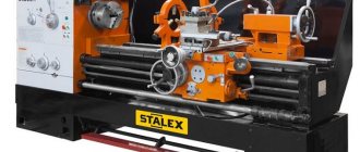
Types and types of Soviet lathes
The classification, developed while the Soviet Union was in force, is still used to this day. The following types of metal-cutting equipment are basic:
- Special.
- Automatic, conventional machines for specialized purposes.
- With several cutters for polishing.
- Frontal, screw-cut.
- Carousel variety.
- Cutting group.
- Revolving.
- Semi-automatic, automatic with several spindles.
- Automatic and semi-automatic with one spindle for metal.