Since a conventional septic tank is not able to efficiently clean sewage, this installation is always built in conjunction with a device for post-treatment. One of the options for organizing soil filtration is a filtration field for a septic tank. Let's figure out how to calculate this structure and build it with your own hands.
High-quality sewerage treatment is an important task that needs to be solved by every owner of a country property who undertakes the construction of a local sewer system.
If you plan to install a conventional septic tank, then a prerequisite for using this installation is additional cleaning. To carry out such cleaning, a drainage field is built. Let's figure out how to calculate this structure and build it yourself.
Types of drainage structures
There are two main drainage systems:
- Drainage well for septic tank. Wells for drainage, which are used when soil and flood waters are deep. The device is an ordinary well that has no bottom. In order to create such structures, rings made of reinforced concrete are used. Now they are used much less frequently.
- Filtration field for a septic tank. This type of drainage is used when groundwater levels are high. This design includes special pipelines that are located in the upper soil layers. The performance of the device depends on the length of the pipelines. The area of the entire mounted structure can be several hundred square meters.
The filtration field is also called the aeration field Source territory-garden.ru
Functioning of the drainage part of the septic tank
Like any device, the drainage field for a septic tank functions according to a certain principle:
- Obtaining clarified wastewater from a septic tank.
- Distribution of wastewater over the area of land.
- Passing through a bed of crushed stone, the wastewater is finally cleaned and the clarified water goes into the ground.
In addition, in some cases, clarified water is drained into a specially designed well for a septic tank.
With proper arrangement of the filtration field, the wastewater is clarified by another 30%, which makes environmental threats less dangerous.
The basis for the functioning of the filtration field is the aerobic method of the cleaning process. The wastewater that comes from the septic tank is cleaned thanks to the air in the system.
With the help of air, organic compounds contained in wastewater are decomposed into elements. These elements do not pose an environmental threat.
Scheme and principle of arrangement of the filtration field
It’s not difficult to figure out how to properly make a filtration field for a septic tank:
- sewage from the plumbing of the house is fed through a pipe into the septic tank;
- suspended substances settle to the bottom of the structure;
- the settled water flows into the distributor;
- The wastewater spreads over the pit area using dispersive tubes and passes through the ground. Filtration from suspended particles occurs;
- Gaseous substances resulting from the activity of bacteria are released from the dispersing system through special ventilation pipes.
Important! The design of the septic tank does not matter for the operation of the filtration field. The main task is to correctly remove and distribute wastewater across the filtration field.
Drainage and sewer pipes are used as dissipative pipes. The required amount is placed at the bottom of a trench or pit, previously filled with a mixture of sand and gravel. The height of the mixture layer is approximately one meter. The sand mixture acts as a filter for wastewater treatment plants.
Device diagram
A drainage diagram is a design drawing that shows the main features of the entire device.
A schematic calculation will allow you to build the correct drainage system Source yaplakal.com
See also: Contacts of companies that specialize in the installation of water supply and sewerage.
The scheme includes the following components:
- the location of the field relative to the septic tank, as well as other devices located on the land plot;
- dimensions of this filtration structure;
- dimensions and number of open excavations in the ground (trenches);
- length and diameter of pipes, parameters of their slope;
- information about the products that are used to install the cushion under the pipes, this also includes the thickness of each specific layer;
- installation locations for pipes intended for ventilation;
- place for drainage of clarified water.
The location of the drainage field should be no closer than 30 meters from any water sources. Such a source could be, for example, a well. The septic tank design should also be located more than three meters from the garden or vegetable garden.
The drainage field should not be located too close to water sources - even clarified wastewater should not fall into a reservoir or well Source infoowalls.ru
The size of the field itself, the length and number of trenches depends on the volume of the septic tank and the estimated rate of wastewater processing. In addition, these parameters are influenced by the characteristics of the soil layer.
If the soil is sandy, then one meter of pipe can be “loaded” with 30 liters of wastewater per day. If the soil is sandy loam, then this figure is halved.
Loamy soil absorbs less water, so the pipe lengthens.
Calculation of the depth of excavation in the soil is carried out taking into account the fact that the bottom must be located above one meter from groundwater. Most often, the depth of the trench is two meters. The width of the excavation depends on the number of pipes and can range from 5 to 10 meters.
Most often, perforated pipes are used for installation, which have an average diameter of 12 centimeters.
Purpose ↑
Filter platforms are used to carry out the process of decomposition of organic substances passing through secondary treatment.
This happens under the influence of microorganisms living in underground drainage. The main purpose of filter fields is to purify domestic wastewater, but they can be used to treat any contaminated water.
The principle of operation is very simple, since it uses the natural processes of the soil to remove various impurities from the liquid passing through it.
To use aeration fields for their intended purpose, the following rules must be observed:
- for best results, install them in loamy soils;
- ditches are prepared in the top layer of earth;
- observe the filling of the trenches, each of them must have a layer of crushed stone, sand and soil. Their correct location is the key to successful filtration;
- the system must be protected from low temperatures and contamination;
- organization of drainage, installation takes into account the groundwater level in the area. May include pipes and a pump to remove liquid from the area. The design of a drainage system occurs through complex engineering calculations.
Photo: filtration fields for a private home
Filtered water can be used for any purpose, even for drinking. This is achieved thanks to two-level waste treatment.
First, they get rid of mechanical substances and inorganic compounds. The biological elements are then removed.
Important! It is not recommended to use cleaning areas for household needs. All organic substances removed from the waste go into the biofilter filler.
Such land becomes unsuitable for growing plants. Every 5-10 it is recommended to replace the filter layers.
Video description
How to choose pipes for a drainage septic tank:
All drainage pipes for the septic tank drainage field must have an equal laying slope - the slope of the drainage pipe per 1 meter is equal to 1.5 centimeters. Every 6 meters, a riser is installed for ventilation.
Sand, with a fraction of up to 10 millimeters, as well as crushed stone with a fraction of 30 millimeters, is used for laying pipelines. In addition, geosynthetics are used, namely geotextiles, which are intended for thermal insulation of pipelines. The material provides additional purification of water waste.
The pipes are “wrapped” in geotextile, sand and crushed stone - these materials trap all large inclusions and additionally protect the pipes from freezing Source infourok.ru
How to arrange a filtration field in clay soil and loam
This type of soil does not allow liquid to pass through well and, accordingly, filters it. It would be possible to dig a pit down to the sand layer, but this is a costly endeavor. However, the filtration field is also available to owners of plots with clayey soil or loam. To do this, it is only necessary to take additional measures when carrying out work:
- spray pipes should be thinner and longer in order to place less load on a specific square of soil;
- at the bottom of the pit you need to fill a cushion of sand or sandy loam 70 cm thick to stabilize the cleansing properties of the soil;
- the crushed stone layer under the pipes should be 30% thicker than for permeable soil.
Attention! The basic load level for sandy soil is 30 l/day. per 1 m of pipe. For clay soil - about 10 times less.
An alternative to underground dispersion is a filtration trench:
- Dig a ditch and fill it with crushed stone or expanded clay.
- Lay polypropylene fabric. It will protect the pipe from clogging and freezing.
- Place pipes with holes inside. Placement depth - up to 0.6 m. The drainage pipe must have a slope of up to 2° from the distribution pipe.
- Cover with soil.
Attention! Sometimes this system also involves the inclusion of a pump in the circuit, which will remove wastewater outside the site.
Installation algorithm
The installation procedure for the aeration field is as follows:
- First, the location where the aeration field will be located is determined.
- A trench of the required depth and width is dug.
- Next, a ten-centimeter soil layer is laid, which has excellent throughput.
- Backfilling of crushed stone with a fraction of 30 millimeters. The thickness of the layer should be 35 centimeters. Pipes for drainage go deep into it. The length of the pipes is no more than 25 meters.
- Connecting pipes to the septic tank and risers for ventilation, which are approximately 50 centimeters high. The ventilation risers are equipped with special umbrellas for protection. The slope is 1.5 centimeters per meter.
- Filling the top layer of crushed stone with a thickness of 10 centimeters.
- Geotextiles are laid from the top of the pipes. This is necessary for insulating pipes.
- A soil layer with a height of 30 centimeters is poured from the top.
The algorithm is suitable for sandy and sandy loam soil cover; for a clayey soil layer, more serious backfilling of the excavation bottom is carried out. The soil that is used to fill the bottom of the excavation must have excellent water throughput. The height in this situation is 70 centimeters.
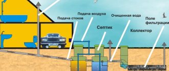
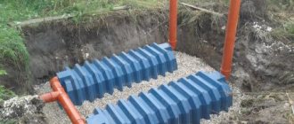
Drainage (filtration) fields of the sewer system - design, principle of operation, maintenance
A drainage field is an artificial structure designed to drain treated wastewater from fecal and other masses from a septic tank or biological treatment system (BTP) and uniformly distribute the discharge for absorption over a large area of the site, photo 1.
Drainage fields, a septic tank, a biological treatment system and other sewerage devices are built where there is no central sewerage system. A drainage field is also installed due to the relatively large volume of wastewater discharge, which a conventional septic tank or SBO is not able to process; the drainage field accelerates the absorption of wastewater into the ground.
Photo 1. Drainage field
Local conditions under which it is imperative to use a drainage field system:
- under different ground conditions, if the GWL (groundwater level) is at least 1.5 m;
- if the filtration properties of the soil are not sufficient to absorb water from the septic tank (well).
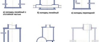
Sometimes the drainage field is called filter trenches, but this is not entirely correct, although the principle of operation is the same. The difference is that the field filter pipes are located on the field (in one large trench), while in filter trenches each pipe is located in a separate pit (trench).
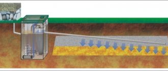
The design of the drainage field can be different, for example, different locations of drainage pipes (drains), photo 2:
- snake;
- parallel arrangement;
- herringbone;
- trapezoidal position.
Photo 2. Location of drainage pipes of the filtration field
Operating principle of the drainage field
- Sewage pipes carry wastewater into the septic tank.
- In a conventional septic tank, rough wastewater treatment occurs - sludge settles to the bottom. In septic tanks of a more complex design, several stages of water purification occur: in the first compartment, the wastewater settles and liquid is supplied through a membrane (preventing the passage of foam and gases) into the second compartment; in the second compartment - under the influence of anaerobic bacteria, impurities and organic matter decompose and ferment, and then they partially float to the surface. In the third compartment or in a separate settling tank, suspended impurities precipitate.
- After separating impurities, treated wastewater enters the distribution well and then into the drains of the drainage field.
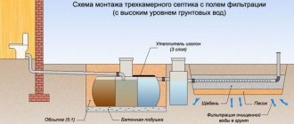
Sequence of drainage field installation
- Geological exploration of the area is carried out, which consists of digging holes in various places to determine the type of underlying soil, groundwater level (groundwater level) and the direction of the natural slope of the site. The drainage field must be higher than the groundwater level (at least 1 m from the bottom of the drainage field to the groundwater level (GWL).
- Determine the location for the installation of the drainage system. The drainage field must be located at a distance of at least 20...50 m from wells and wells, photo 3. Neglecting this condition can lead to contamination of drinking water in the well.
Photo 3. Requirements for the location of the drainage system
- According to the table 1 determine the type of drainage system device, in this case, a drainage field. From the table 1 shows that the best soil for drainage is sandy, sandy loam or light loam.
The sand cushion should be below the soil freezing depth; can be located above the freezing level, but additional insulation should be laid (to reduce the freezing depth in a local area).
The length of the pipes is determined by the absorbent (drainage) capacity, which is approximately the following:
- sandy soils – 30 l/day per 1 m.p.;
- sandy loam – 15 l/day per 1 m.p.;
- loams - 5...6 l/day per 1 m.p.
The construction of a drainage field on clay soils is ineffective, since the water absorption capacity of clay is very small. Practice shows that replacing clay soils with sand is an expensive undertaking and it will be cheaper to install modern mini-integrated systems for autonomous wastewater treatment.
Table 1
Construction of a drainage field for different types of soil
| Type of soil | |||
| Clay | Loam | Sandy loam | Sand |
| 1. Clay should be completely replaced with river sand up to 3 m deep.2. Lay a layer of crushed stone with a thickness of 0.35...0.5 m and a fraction of 10...20 mm or gravel with a fraction of 12...32 mm.3. Laying drainage pipes. 4. Backfilling the pipes with a layer of sand 0.5 m thick. 5. Backfilling the pit with soil. | 1. Partial replacement of loam. Mixes half and half with river sand to a depth of 3 m.2. Lay a layer of crushed stone with a thickness of 0.35...0.5 m and a fraction of 10...20 mm or gravel with a fraction of 12...32 mm.3. Laying drainage pipes. 4. Backfilling the pipes with a layer of sand 0.5 m thick. 5. Backfilling the pit with soil. | 1. Partial replacement of loam. The soil is mixed with river sand to a depth of 3 m according to the following proportion (70% sandy loam and 30% sand)2. Lay a layer of crushed stone with a thickness of 0.35...0.5 m and a fraction of 10...20 mm or gravel with a fraction of 12...32 mm.3. Laying drainage pipes. 4. Backfilling the pipes with a layer of sand 0.5 m thick. 5. Backfilling the pit with soil. | 1. Dig a trench.2. Lay a layer of crushed stone with a thickness of 0.35...0.5 m and a fraction of 10...20 mm or gravel with a fraction of 12...32 mm.3. Laying drainage pipes. 4. Filling the pipes with sand. |
Other sources indicate that after installing pipes (drains), a layer of crushed stone 10 cm thick and a geotextile film should be laid on top of them, and a layer of previously removed soil should be laid on top of the film.
- A pipe with a diameter of 110...160 mm with a slope of 5...10 mm/m is laid from the wastewater discharge point (from the house) with a layer of cushion and backfill according to Table 1. The depth of the pipes should be within 0.45...0.65 m. When installing the system at the level of soil freezing, a layer of thermal insulation is laid.
- A horizontal septic tank (sump tank) is installed at a distance of 4...5 m from the house, photo 4. The depth of the septic tank should be no more than 1.25...2 m.
Photo 4. Construction of a drainage septic tank and field
6. After the settling tank, it is advisable to install a distribution well, which is designed to regulate the level of wastewater, photo 5.
Photo 5. Construction of a drainage system with a free-standing distribution well
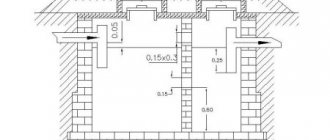
7. From the distribution well there are distribution perforated pipes of the drainage field. For optimal distribution of wastewater in drainage pipes, perforations (holes) of different diameters are made - in the upper part of the pipe there are holes of small diameter, but in large quantities, and in the lower part of the hole there are larger diameters, but in smaller quantities. The distance between adjacent drains (pipes) must be at least 1.5...2 m, photo 6. The width of the trench for the pipe (for filtration trenches) must be at least 0.5 m (preferably 1 m), and the depth 0.8 ...1.5 m. The length of the trenches should be no more than 20 m, the optimal option is 15...18 m. The total length of the drainage field is determined from the following calculation:
- on average per 1 consumer 12 m.p.;
- with sandy soil per 1 consumer 8 m.p.
To prevent siltation of drainage pipes, they should be covered with geotextile film (photo 7).
Photo 6. Scheme and parameters of the drainage field and trench
Photo 7 Installation of geotextile material
8. At the end of the drainage field pipes, ventilation should be installed in the form of vertical pipes, photo 8. In long drainage fields, ventilation pipes are installed every 5...7 m. Ventilation allows free flow of air into the pipes and ensures the normal functioning of anaerobic bacteria. Under optimal conditions, wastewater purification of up to 95% is achieved.
Photo 8. Ventilation device for the drainage field
Advantages of using drainage fields
- Relatively long service life. A properly and competently installed drainage field system with moderate use lasts from six to several decades. To increase the service life of the drainage field and its normal operation, the possibility of storm and melt water, insoluble impurities and compounds, alkalis and acids, in particular chlorine, entering the system should be eliminated as much as possible.
- The first 10 years require very low maintenance costs for the drainage field.
- Sufficient wastewater treatment.
Disadvantages of using drainage fields
- Major repairs of a drainage field (replacement of drainage layers) is a labor-intensive and costly process. Typically, major repairs are performed every 6…10 years.
- It occupies a large area, which is not recommended for planting trees or growing vegetables.
- The high cost of installing a drainage field. The approximate cost of installing a drainage system with a field of 25 m2 is $2200...2400.
Drainage system maintenance
When servicing the drainage system, special attention is required to the septic tank and drainage field. The settling tank should be periodically inspected and the level of sludge should be determined. If the level is high, it should be pumped out using a vacuum truck. This procedure should be performed at least once a year in order to prevent sludge from entering the distribution tank or pipes of the drainage field, which will lead to clogging of the holes in the pipes and pores in the soil and disruption of the functioning of the entire system as a whole. To increase the durability of the drainage system, it is necessary to carry out preventive measures - once every 2...3 years, it is necessary to flush the drains with iron hydroxide. A hose is connected to the outlet pipe of the septic tank and an aqueous solution of iron hydroxide is supplied under pressure.
It is prohibited to drive vehicles or plant trees with a deep root system in the area where the drainage field is located.
Nowadays, for the installation of drainage fields, you can use ready-made pipes with additional insulation and components, for example the SoftRock system.
The SoftRock drainage field system is a more advanced version of a conventional drainage field. A feature of the SoftRock system is the use of crushed cubic foam as a drainage material (instead of crushed stone), enclosed in mesh and geotextiles, photo 9.
Photo 9. Drainage fields of the SoftRock system
Advantages of using the SoftRock system
- increased effect of wastewater removal (reaches 35...50%);
- easy installation process without the use of equipment, due to the light weight and length of the pipes;
- increased flexibility of pipes allows you to bypass obstacles that may stand in the way of drainage (trees, structures);
- the drainage pipes of the SoftRock system are able to withstand pressure from a layer of soil more than 2.5 m thick and the load from cars weighing up to 25 tons, so this system can be used in parking lots;
- greater durability of the system compared to a conventional one, due to less clogging of the drainage with small particles of soil or solid particles contained in wastewater.
The author of the publication is an expert from GIDproekt
Konev Alexander Anatolievich
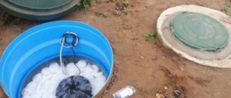
Dosing chamber
The dosing chamber will ensure the gradual removal of liquid into the drainage field Source nk.pl
The dosing chamber is a container that has a capacity of up to 1 cubic meter. For construction, a ready-made plastic container corresponding to the required volume can be used.
The bottom of the excavation is leveled, where the container is then loaded. Uninterrupted operation of the system at the outlet of the tank is achieved by installing a siphon, which has a diameter of 100 millimeters and an elbow height of 200 millimeters. As the siphon fills, it will self-charge, then self-empty. Thanks to this, the purified liquid is supplied to the pipelines for distribution.
Drainage tunnels
Drainage tunnels are a type of filtration fields. This design is chosen if a huge amount of water is discharged. A distinctive feature of the device is its increased cross-section, which ensures high cleaning speed. The advantage of drainage tunnels is a high level of mechanical stability, which makes it possible to install a post-treatment field, which can even be located under a parking lot.
Algorithm for installation of the structure:
- Digging trenches up to two meters. At the bottom of the excavation, a sand “cushion” is created, having a thickness of 50 centimeters. On the top there will be a layer of crushed stone 30 centimeters thick.
Construction of drainage tunnels Source fishing-caravan.ru
- The modules are being . Before installation, the surface must be leveled and compacted. The external walls of the modules are covered with geosynthetic.
- Elements are connected . The branches of the structures are connected to the exits from the septic tank.
- Installation of ventilation . Ventilation outlets are installed in the openings of the structures.
Geogrids are also installed to evenly distribute the loads over the structures.