What is a collector water supply scheme
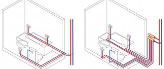
A collector water supply scheme is the distribution (laying) of water pipes from a single distribution device to each water consumer (plumbing device) of the apartment independently of each other. Moreover, each device can be disconnected from the water independently.
At the same time, you need to understand that the apartment essentially has two water pipes. One for cold water (CW) and the second for hot water (DHW).
The device from which the water supply is extended (installed) is called a collector. In the apartment's water supply collector circuit there should be at least two of them, for cold and hot water.
Collectors are installed after the apartment's water supply system in specially made plumbing cabinets.
Collective water supply distribution in the house - disadvantages
First of all, let's deal with the pressure in the system, which is correctly called calculating the required pressure. I wrote about this in some detail Calculation of a surface pump: how to calculate the pump pressure.
It is by calculating the pressure that the required pump is purchased for the source of water supply to the external part of the water supply of the house.
In this calculation, a large share is made up of losses due to the hydraulic resistance of pipes. The chain is obvious: the more pipes, the greater their resistance to flow, the greater the resistance, the greater the pressure required, the greater the pressure, the more powerful (read more expensive) a pump is required to deliver water from the source.
The collector distribution of the water supply system in the house differs from the tee distribution precisely in the large number of pipes in the system. After all, a separate pipe needs to be connected to each consumer, and more often than not one (CHS and DHW). This is why collector wiring requires increased water pressure.
Hence, the collector distribution of the water supply system in the house cannot be used with the selected gravitational water supply system. Let me remind you that the gravitational scheme of the water supply system is the independent spreading of water under the influence of gravity from the highest point in the house.
In addition, it is necessary to take into account that to the calculation of the pressure it is necessary to add the pressures of each section from the collector to the consumer. This is insignificant, but still, an increase in the required pressure of the purchased pump.
An increase in pump costs is only the beginning of additional costs for the water supply system in the house. Costs will increase for the purchase of water pipes, which will be needed an order of magnitude more than in a sequential scheme.
Another minus, already the third. If you live in a house only in the summer, and in winter you live on short visits, there is another serious disadvantage of using water supply collectors. Every time I leave my winter dacha. You will have to drain the water from each ray of the collector wiring.
Advantages and disadvantages of a collector water supply system
Among the undoubted advantages of the collector water supply scheme, I would include
- Ease of maintenance of the water supply system. You can turn off any device independently of others.
- Possibility of connecting new household appliances with pipeline connections without dismantling the existing water supply circuit.
The disadvantages of the collector circuit include the increased cost of plumbing installation work and the consumption of more materials, since a separate pipeline must be connected to the devices.
Also, high-quality water distribution using a collector circuit can only be done during a major renovation of an apartment bathroom.
Leak protection system
Even the most reliable and modern water supply system includes connections with sealing gaskets and flexible hoses. According to statistics from insurance companies, these elements are the main causes of leaks in the apartment.
In order to protect yourself, you need to install a leakage protection system. The system consists of a ball valve with a servo drive, a control module and sensors. When water hits the sensor, the system gives a command to close the tap.
It is important to note that the leakage protection system should be installed immediately after the shut-off valve - this will help minimize the number of unprotected connections.
Read more about the leakage protection system >>
There are a large number of protection systems on the market, but our company recommends installing the Akvastorozh system. It has proven itself well, and the manufacturer provides good, timely service.
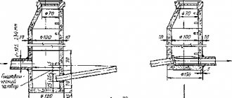
Water supply collector diagram drawing
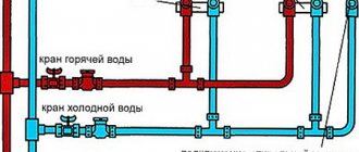
The figure below shows a water supply diagram using a collector circuit. This is a common option offered as an example.
Manifold water supply wiring diagram
See the diagram above.
- 1.3 - Ball valves for heated towel rails;
- 2 - Ball valve to the bypass jumper;
- 4 - Main, emergency ball valve for hot water;
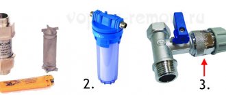
- 5 - Coarse filter;
- 6 - Accounting counter;
- 7 — fine filter with a brass mesh 100 microns;
- 8 - Pressure reducer, for houses without booster pumps;
- 9 - Collector;
- 10 - Main, emergency ball valve for cold water.
Classic wiring diagram
The usual layout of water supply pipes around the house is tee or sequential: a pipeline is drawn from the main riser, to which the necessary devices and equipment are connected through tees and bends.
This connection technology is advantageous in the following ways:
- Minimum total pipe length;
- Low hydraulic resistance in the water supply system.
In practice, this scheme has not proven itself to be very good - it turned out that it was better to implement the connection through a comb. The disadvantage of the traditional connection is that when several valves are opened simultaneously, the pressure in one of them, or in both, drops.
What is a collector
A manifold, or comb, is a plumbing device that has one input and several outputs. Control valves are installed at each outlet to change and shut off the water flow. Copper, steel, polymer, and metal-plastic water pipes can be connected to the collectors.
Manifolds are available with the ability to connect water supply from both sides. During installation, one input is plugged. Collectors are available with different numbers of leads. The most common collectors are 2,3,4,5,7 pins. Manufacturers are very diverse. Depending on the company, the price and quality of collectors differ. Here is a list of manifold manufacturers selling in Russia:
- VALTEC Russia;
- Italian company Far;
- German Rehau;
- Italian Tiemme;
- Italian Luxor;
- UNI-FITT Italy;
- Polish Solomon.
Manufacturing methods
Before you start making a homemade collector, you need to select the material and prepare the necessary equipment. For example, to make a steel model you will need a welding machine. But don’t rush to choose polypropylene. In order to connect polypropylene parts, you will need a special device that is used to weld such pipes. Sometimes it is easier to get an ordinary welding machine than for plastic.
Calculation and distribution of contours
From the very beginning, you need to understand how many heating circuits you will need. It is necessary to take into account each existing heating device, so you will have to evaluate each room according to the list below.
To avoid forgetting anything, use the following list:
- the presence of a “warm floor” system;
- rooms that should have a higher or lower temperature compared to other rooms;
- floor heating;
- heating of each wing.
The rules for manufacturing a heating collector are as follows: the distance between the taps is 10-15 mm, the distance between the supply and return collectors is 25-30 cm.
The diameter of the pipes should be 12.7 mm. The collector itself is made with a diameter of 25.4-38.1 mm, depending on which boiler is installed.
Made from polypropylene
To make a polypropylene manifold assembly with your own hands, you will have to use leftover pipes and fittings.
You will need:
- pipe with a diameter of 32 mm;
- tees 32/32/16 mm.
A tee must be installed on one side. An air vent must be connected to it at the top, and a drain tap at the bottom. On the other side, a valve and pipe are attached. The pipe can be supply or outlet, depending on the purpose of the collector. The supply pipe goes to the boiler.
The remaining outlet with a diameter of 16 mm must be equipped with a valve or flow meter, depending on which collector is for water supply or outlet. At this point the work is completed, and all that remains is to secure the resulting collector systems to the wall using brackets.
Assembly of brass fittings
If a ready-made brass manifold is quite expensive, then you can spend much less money on a homemade one. To build such a structure you will need tees and fittings. They are connected to each other using linen tow or a liquid fixative as a cushioning material. The parts must be connected according to the assembly diagram. An example can be seen in the picture below.
After the collector is assembled, it must be tested. It is difficult to make the connection correctly, so the likelihood of leaks is high.
From a profile pipe
Making a collector from pipes with different cross-sections is the most difficult, since it will require welding work. This model can be called the most “sophisticated”. It is suitable for heating large areas and can have many pipe connections. Often such samples are equipped with a hydraulic arrow.
The following samples will be needed:
- profile pipe 8x8 cm or 10x10 cm;
- round pipe.
The calculation of the pipe cross-section is performed in special programs. It is necessary to set the required heating thermal power, water speed, temperature difference between supply and return.
In this case, you will need to build a circuit, taking into account the number of circuits. Remember that the distance between wiring should be about 15 cm, and between collectors - at least 20 cm. A typical diagram looks like this.
Next, you need to mark a pipe with a rectangular cross-section according to the diagram, and then make holes for wiring using a gas cutter. Weld pre-prepared small parts of threaded pipes to the holes. The block is ready, all that remains is to weld the brackets to it, prepare it and paint it.
Operating principle of a water supply collector circuit
The operating principle of the water supply collector circuit is very simple. Water under pressure enters the manifold and is distributed through the outlet outlets. Each collector outlet has its own control or shut-off valve.
Collector shut-off valves, theoretically, do not regulate the water supply pressure into the apartment’s water supply system. The water is completely shut off in half a turn. Such valves are designed for about 4000 cycles, turning off and on.
Control valves can regulate the flow of water, like a faucet faucet. A very convenient thing, especially if your house has strong water pressure. Rated for 8000 cycles.
Features of the design of water supply in home heating
If the heating system is made according to a combined scheme, then the radiators work in tandem with the pipeline of the “warm floor” system, and the water supply collector is equipped with a mixing unit so that when the liquid in the heated floor circuit cools, water from the collector is added to this circuit by mixing.
When purchasing a ready-made manifold, it is recommended to pay attention to the distances between the outlets of the supply and return manifolds, since in Asian devices these values may not correspond to European standards, and the water mixing unit may simply not fit.
Manifold for water heated floor
The manifold for “warm floors” has outlet pipes Ø 16 mm, 18 mm and 20 mm. For highways laid in country houses, it is recommended to install pipes with Ø ≤ 16 mm. If there are several “warm floor” circuits in the house, and they have different lengths, then the collector needs a balancing system with a flow meter, since without a balancer, the floor with a shorter pipe route will always be hotter.
By rotating the ring on the flow meter, its throughput capacity is changed, and therefore the temperature in the circuit is regulated. The hot water consumption is visually controlled through a special slot with a scale.
Rules for installing water supply systems
For the water supply main, collectors are also installed in two units: one collector is for hot water supply, the other is for cold water supply. When implementing such a solution, no control valves will be needed - only shut-off valves or taps are installed. Such taps in the cold water supply line are equipped with blue handles, for hot water supply - with red handles. The main water supply manifold pipe is installed in a dry place, but the ideal solution would be to install a separate cabinet for the manifold. For this purpose, factory units are equipped with special fasteners, and there are places for them in factory cabinets. When making a collector with your own hands, the method and scheme of placement and fastening of the collector will need to be thought out separately - choose any option that ensures the conditions described above.
Design and operating features
A manifold is a plumbing comb-distributor, which is a hollow cylindrical element in the form of a pipe. On one of its sides there are branches located in parallel. The diameter of the inlet hole is always 25-40% larger than the outlet hole. This design of the comb ensures uniform distribution of the flow of cold or hot water across the points.
The water supply system collector is integrated into the main riser. For attachment, internal and external threaded connections are provided. Using them, if necessary, you can add an additional distributor. A plug or water hammer absorber is mounted on the unoccupied end. Valves or ball valves are installed at the outlet outlets, designed to regulate the pressure or completely shut off the water.
Distribution manifolds are mounted on the wall, usually in the bathroom or toilet. They must always be accessible, so the entire system is usually hidden in a collector (plumbing) box.
Main water filters
There are situations when the quality of water is very poor - it has odors and all kinds of impurities of chemical elements that are harmful to human health. In these situations, main water filters are used. Filter elements are selected based on the results of laboratory water tests. When installing a main filter, it is advisable to provide a bypass (jumper) - this will allow you to use water when replacing the filter.
We recommend using main filters with stainless steel flasks in your apartment, as they have a long service life, are not subject to corrosion, and have a simple procedure for replacing the filter element.