Malfunctions. Repair.
If you decide to carry out repairs or adjustments yourself, make sure you have the necessary qualifications. Poor repair of gas equipment can cause a fire, explosion or poisoning. After completing the work and assembly, make sure that the device is tight and operates correctly. The tightness is checked by applying a soap solution to all joints. No bubbling indicates there is no leak. But you shouldn’t delude yourself. The tightness will need to be checked several more times (after a day, three days, a week of operation), and then checked regularly, since a leak may occur some time after the start of operation.
Main malfunctions: the gas pressure at the outlet does not correspond to the nominal value (reason: the spring is broken or deformed), gas leakage (reasons: the membrane is damaged, the tightness of the connection between the membrane and the housing is broken, the float valve is leaking)
Here is a selection of materials:
Everything you need to know about heating and climate control Features of the selection and maintenance of boilers and burners. Comparison of fuels (gas, diesel, oil, coal, wood, electricity). Do-it-yourself ovens. Coolant, radiators, pipes, heated floors, circulation pumps. Chimney cleaning. Conditioning
If the float bypass valve leaks, then the leak may not occur in the reducer itself, but somewhere further, for example, in a gas stove, since in this case, in zero consumption mode (when the stove or some other consumer is turned off), at the outlet reducer and gas pipes, the pressure can reach the inlet pressure. Gas gradually leaks through the valve, and there is nowhere for it to go. If there is a gas cylinder at the inlet, the pressure can reach 15 bar, which is 500 times higher than the nominal one. Such pressure will definitely lead to leakage. At the same time, it is difficult to detect this malfunction, since when the stove is turned on, the pressure normalizes. There is no sign of overpressure (flame blowout). The fault can only be identified by measuring the outlet pressure in zero consumption mode. It can be no more than 20% more than nominal.
To repair, the gearbox must be disassembled. Only a dismountable gearbox with a spring can be repaired. Sealed gearboxes are not suitable for repair.
In the picture, the membrane is with the bottom side up.
An inspection will show if there are defects in the membrane or a broken spring. A torn membrane can be replaced. But it’s not worth it, it’s better to buy a new gearbox, since it’s quite difficult to hermetically connect the new membrane with the washers. A broken spring can be replaced. Most often, the spring does not break, but simply compresses a little over time. As a result, the outlet pressure becomes lower than nominal. This malfunction can be easily corrected by placing a gasket between the housing and the spring. Read about this below in the section on transferring to another pressure.
Membrane - top view.
If you have diagnosed problems with the bypass valve, then you need to inspect it. It is a tube with a thin hole. A piece of hard rubber mounted on a rocker arm is pressed against the end of the tube. The valve may not close for the following reasons: Firstly
, the mobility of the rocker arm is impaired.
Move it with your hands, make sure it moves freely. If there are problems, grind or replace the hinges. Secondly
, a piece of rubber was worn out and torn.
It can be removed with a sharp knife and replaced by gluing another one of the appropriate size in its place. Thirdly
, the end of the inlet tube may not be smooth, with damage and roughness. This prevents a tight seal. The end can be sanded with fine sandpaper.
Very often, a leak occurs due to a leak in the seal between the membrane and the lower part of the housing. Troubleshooting is easy. You need to lubricate the edge of the lower part of the case where the membrane fits with silicone sealant, let it dry a little (10 minutes), install the membrane, assemble the gearbox and let it dry a little more (2 hours).
During disassembly and subsequent reassembly, it is quite easy to break the tightness of the membrane. If you have disassembled the gearbox, then during reassembly in any case, even if there was no leakage, use silicone sealant. This will improve reliability.
LPG gearbox repair
Most car owners have begun to switch to gas fuel, this is explained by the fact that gasoline prices increase quite often. And in order to save money, gas equipment is installed on the car. It is worth noting that in connection with its installation, the driver has new worries. Because the gas system needs to be adjusted and configured, which is most important, this happens not only at the time of installation, but also during operation.
It is worth noting that adjustment occurs with increasing vehicle mileage. This is explained by the fact that after a certain time, usually 3-4 years, elements made of rubber - membranes, valves - lose their primary properties. And this leads to increased fuel consumption.
One of the most important parts is the LPG reducer; below we will consider in detail its properties, significance, as well as how to properly configure and adjust it.
Conversion to a different pressure
Sometimes it becomes necessary to obtain non-standard pressure at the outlet. For example, having bought a stove for natural gas, I wanted to convert it to a bottled one. The usual way is to replace the injectors and low gas flow screws, but there is another way - to use a 12 mbar reducer. Such reducers are commercially available, but they are rare and difficult to buy. You can remake the usual one.
I will say right away that not every reducer can be converted to any pressure. There are the following restrictions. The ratio of the areas of the membrane and the inlet port, multiplied by the rocker arm, should be one and a half times greater than the ratio of the maximum inlet pressure and outlet pressure. Otherwise, the force developed by the membrane under gas pressure will not be enough to reliably close the inlet valve. In practice, it is usually easier not to carry out these calculations, but to configure the gearbox experimentally. All the same, to carry out calculations it needs to be disassembled in order to measure the area and lever of the rocker arm.
For remodeling, it makes sense to buy a gearbox in which the mounting screws are accessible and not covered in paint. The modification comes down to changing the elasticity of the spring. Let's disassemble the gearbox. If the pressure needs to be made less than it was, then shorten the spring a little (by half a turn), if more pressure is needed, then place a spacer between the gearbox housing and the spring. When installing the gasket, be careful not to block the hole in the housing. We assemble and check the gas pressure at the outlet. Repeat until the desired pressure is achieved. If after the next shortening the pressure turns out to be less than necessary, then the spring can be stretched a little or a gasket can be placed.
The principle of operation of a gas reducer on a car
Each element of gas equipment performs a specific function. Fuel consumption and the operation of the vehicle engine in general depend on the coherence of the entire system. The key role in this complex scheme is played by the gas reducer.
How does a gas reducer work, why is it so important to maintain it in perfect working order? The answers to these questions will help car owners navigate the choice of this device and recognize gas equipment problems in a timely manner.
What is a gas reducer?
The principle of operation of the gas reducer in household gas cylinders, in the main gas pipeline network, where pressure adjustment is required, in the gas equipment of cars, is similar. This device is designed to reduce the pressure of gas fuel and maintain this pressure at an optimal level.
If the device does not cope with its functions, the safety and performance of the gas system will be at risk.
In all cases, the task is the same: to ensure that the gas pressure is always at a given operating level.
To understand the principle of operation, the device can be divided into series-connected zones separated by valves. The most important of them, the unloading one, additionally performs the function of an injection dispenser. The device contains an evaporator, as well as an idle channel.
On a note! In innovative gas equipment kits of the 5th and 6th generations, installation of a gearbox is not required: gas injection occurs in a liquid state.
On what principle does the device work?
The temperature of the antifreeze should rise to 40. The operation of the gas reducer is possible only after the car has warmed up well. How does a gas reducer work on a car?
Tomasetto 4th generation gearboxes
The following happens:
- Liquid gas from the reservoir enters the filter and is purified. There it remains while the solenoid valve is closed.
- The fuel then passes through the 1st stage valve seat and turns into steam. The membrane, under its pressure, pulls back the valve rocker arm, it lowers onto the seat and the gas flow stops. This gives a working pressure of 0.4 atm. It is adjusted by a spring mechanism.
- Automotive gas fuel moves further to the 2nd stage valve seat. The fuel then goes through the outlet fitting to the engine.
Idling
The fuel supply to the 2nd stage is controlled by the valve load. The adjustment screw rotates through a spring mechanism. The elastic membrane “freezes” in equilibrium. In this case, the vacuum from the internal combustion engine at idle is compensated by the load of the spring mechanism. This is the principle of operation of the LPG gearbox at idle speed.
What happens after the valve opens?
The throttle valve opens and the ejection process occurs. The 2nd stage diaphragm plate deflects in proportion to the load experienced by the motor. It pulls the valve rocker, opening the seat and increasing the intensity of the fuel supply. Such actions automatically increase engine speed.
Operating principles of gearboxes in various generations of gas equipment
Despite the fact that the principle of operation of the GBO gearbox of generations 1, 2, 3 and 4 is subordinated to a single task, the equipment of the device varies depending on the generation. The unloading compartment locking methods and settings are also different.
1st generation gearbox
In the 1st generation there was a vacuum device of a mechanical type. The membrane plate responded to the vacuum in the intake manifold, to which an additional line was extended.
When the engine started, the carburetor began to draw in fuel, the pressure dropped, and the vacuum valve opened the way for fuel. The engine was turned off, the pressure returned to normal and the fuel inlet was blocked. The device was adjusted simply: by mechanical rotation of the greed screw.
These are the main differences in the operating principles of the gas reducer of the 1st and 2nd generations.
Gas equipment for diesel: how realistic is it?
2nd generation gearbox
The operating principle of the 2nd generation gas reducer has evolved. Now this is not a vacuum, electronic device. An important addition: it is equipped with a solenoid intake valve controlled by the power unit.
This ensured an automatic response of the device to starting the car engine. The solenoid valve supplies gas based on impulses from the oxygen sensor.
This is the main advantage of an electronic type device, since older carburetor engines do not always have enough vacuum for the membrane to work.
Gearbox 3rd and 4th generations
In the 3rd and 4th generations of HBO, this device is simplified in design. Some options have been transferred to the collector. There is no need for a large number of membrane partitions. For a split injection system, 2 stages and one solenoid valve are enough.
The number of sensors has become larger in number. A complex design filter device was added to ensure gas purification.
The mechanism has become more convenient to configure. The electronic control unit is connected to the laptop. A special program is launched that performs configuration and diagnostics. Devices from the brands Tomasetto and Lovato are easy to adjust.
The operating principle of the gas pressure reducer must be taken into account when choosing this device. Pay attention to what generation it belongs to, whether it has dust and moisture protection. Power characteristics should be with reserve. But the dimensions must correspond to the area that can be allocated to the device in the engine compartment.
Classification depending on the scope of application
Depending on the scope of application, reducers for gas cylinders are divided into several types:
- Household unregulated.
- Universal adjustable
- Professional.
Household unregulated
This type includes the simplest gearboxes used in domestic gas supply to households and in camping conditions. RDSG reducers are installed together with household gas cylinders. They have the simplest design, allowing the use of gas only in household stoves and are inexpensive and reliable. The frog reducer for a gas cylinder, or RDSG-1, is used in conjunction with containers from 12 to -50 liters.
For five-liter gas cylinders, popular among summer residents, tourists and hunters, the RDSG-2 Baltika model is used. The Baltika reducer is put on the nipple of the gas cylinder from above and fixed in the rubber seal with a special clamp. The gearboxes are configured for an operating pressure of 0.3 MPa and a throughput of 1.2 m 3 / hour
Universal adjustable
This class of gearboxes has a more complex design and wider capabilities. They can already be used both for domestic gas supply and for work in a home workshop. These reducers have a mandatory threaded connection to the gas cylinder, which securely locks the device.
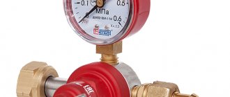
Universal adjustable for propane with pressure gauge
They are also equipped with a pressure gauge and an adjusting screw that allows you to change the operating pressure from 0 to 0.3 MPa, depending on the needs of the gas consumer device connected to them. These devices also have a greater throughput than household ones - up to 5 m 3 / hour
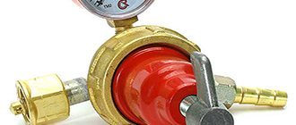
Professional
This class is characterized by the use of more wear-resistant materials and better build quality and adjustment. The operating pressure adjustment parameters are also wider – from 0.4 to 1.6 MPa.
Professional gearbox with two pressure gauges
Some models are equipped with two pressure gauges - for inlet and operating pressure, respectively.
Advantages
A gas cylinder for a summer residence has some advantages:
— Easy to use and replace.
— Mobility
. Naturally, there are certain rules for installing the device, but in general it is not limited to one place, like a boiler.
— Various types of containers.
Depending on the purpose for which the device will be used (cooking, heating), you can purchase one or another cylinder (5, 16, 18 or 50 liters).
— Possibility of refilling the container
.
As you can see, even in the absence of centralized heating, a gas cylinder in the country can make life comfortable and convenient.
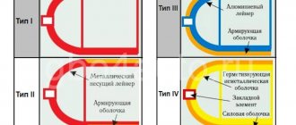
Features of using composite gas cylinders
Composite gas cylinders have recently become increasingly popular. This is due to their advantages over their steel counterparts.
- Weight. Almost twice as light as steel.
- Ease of handling. There are comfortable handles.
- Transparency. The fill level can be easily seen.
- Convenient storage. Can be placed one on top of the other and stacked.
- Life time. The service life is practically unlimited.
- Operational safety. It is caused by the absence of sparking and a safety valve and fusible link built into the gas cylinder.
What is a propane reducer?
The design of all propane reducers is very similar. They all have:
- Sealed housing made of aluminum, brass or plastic.
- Inlet pipe for connection to the cylinder.
- Outlet pipe for connection to the consumer.
- High and low pressure chambers.
- Flexible membrane.
- Valve and stem.
- Return spring.
- Working spring.
In professional gas reducers, a pressure gauge, an adjusting screw or flywheel, and a threaded connection of the supply pipe are added to the design. The gearbox housing has a cylindrical shape, which is due to the use of a round membrane that bends inside the operating pressure chamber. The inlet and outlet pipes protrude from the housing.
How to choose a reducer for a household propane cylinder
To select a propane reducer for a gas cylinder, it is necessary to study and compare their characteristics. The most significant are:
- Purpose.
- Maximum inlet pressure, kg/cm3.
- Working pressure, kg/cm3.
- Maximum gas consumption, m 3 /hour.
- Connection standard.
- Planned service life.
- Price.
Depending on the planned application and the planned type of cylinder, one or another model may be the best choice. So, for example, if you plan to connect a tabletop gas stove in a garden house that you visit on weekends (or take it on a boat trip) and estimate your monthly gas consumption to be five liters, a five-liter cylinder and a Baltika RDSG-2 gas reducer are best suited.
Gearbox Baltika RDSG-2
For a stationary stove with an oven, you will already need a cylinder with a capacity of 27 or 50 liters and, accordingly, a Frog RDSG-2 gearbox.
If you want to connect a composite cylinder to a thermal umbrella, and both the cylinder and the umbrella have European connectors, then it makes sense to consider imported gas reducers with a KLF connector, for example, produced by the German company GOK.
If you plan to carry out gas welding in a home workshop, then a professional gas reducer BPO 5-3 Krass would be a good choice. It provides a maximum flow rate of up to 5 m 3 per hour and the ability to regulate operating pressure up to 0.4 MPa. To do this, it is equipped with an adjusting flywheel and a pressure gauge, which allows you to more accurately set the operating pressure in accordance with the needs of the gas welding torch or cutter.
How to choose
One of the most common choices in this class of devices remains the RDGS-1 device, the main advantages of which are its affordable cost and simplicity of design. RDGS-1 is produced in Russia and Belarus; below are the main characteristics of the device:
- Input pressure value 0.07 – 1.6 MPa
- Output pressure 2950 – 3300 Pa
- Gas consumption 1.2 m3/hour
- Weight 310 g
- Operating temperature range -30°С +45°С
Reducer RGDS-1
Instead of the time-tested gearbox RDGS-1, the price of which is 150-200 rubles, you can buy a more modern model. For example, the Italian device m714, which costs a little more (about 250 rubles).
Typically, this reducer is supplied complete with a Pullover1 gas heater, but it can also be purchased separately. The gearbox is equipped with a gasket made of elastic material, which has a five-time use life. The input pressure of m714 is in the range of 0-20 Bar, and the output pressure is 30 mBar.
Often, to connect composite cylinders to burners, a German-made GOK model costing about 500 rubles is used. However, there are also more expensive models.
Thus, the N240 gearbox, which costs more than 1000 rubles, has the following characteristics:
- Inlet pressure up to 18 bar
- The output pressure can be adjusted within the range of 20 – 60 mbar
- Productivity – 4 l/hour
- Operating temperature range -20°С +50°С
Gearbox N24
Another type of gearbox, called miniature, has become widespread among gas cutters. A prominent representative of this class can be considered the BPO-5 general purpose gearbox, the main technical characteristics of which are:
- Input pressure value up to 2.5 MPa
- Output pressure value up to 0.3 MPa
- Weight 0.65 kg
It must be remembered that purchasing and installing a reducer for a gas cylinder is a serious and responsible step. Not only the quality of operation of gas appliances, but also the safety of everyone who will use this appliance largely depends on the correct choice.
Central heating, unfortunately, is not available everywhere. In this case, either a stove or a gas cylinder can save you. For a summer residence, this option is optimal. However, this device also has its own characteristics.
Precautionary measures
Household gas is very dangerous. The main threats posed by propane are:
Reminder about domestic gas
- Fire hazard.
- Unsuitable for breathing.
- Explosion hazard when the maximum concentration of propane in the air is reached, as well as when the temperature in a closed volume rises sharply.
- During a gas leak, the temperature drops sharply and frostbite is possible.
To preserve the life and health of people and their property, precautions should be taken:
Rules for using gas
- Avoid proximity to open flames and heat sources.
- Avoid the presence of other flammable materials in the work area.
- Eliminate the presence of nitrates and perchlorates near gas equipment due to their chemical activity.
- Do not use the reducer for a propane cylinder if it is damaged or leaking.
Design features and maintenance
According to their design, gearboxes differ into direct and reverse acting devices. The differences between them are in the design details, the performance characteristics are identical.
Design of gearboxes for a gas cylinder
In addition, gas reducers are used in single-stage and two-stage types. In single-stage, the pressure is reduced in one stage. In a two-stage reduction, the reduction is carried out in two steps. Balloon single-stage reducers are most widely used due to their reliable design and ease of use.
Sequence of installation and use
A propane reducer of any type and design is considered a high-risk technique, therefore, when installing it, a number of mandatory requirements must be observed:
A reducer is necessary to reduce the gas pressure that comes from a cylinder or gas pipeline to operating pressure and maintain it in the range you need in automatic mode. If there is a change in pressure in the system, this does not in any way affect the operation of the gearbox itself. Gas reducers are divided into two types based on their operating principle.
A simple gearbox consists of the following parts:
Diagram of direct and reverse acting devices
Direct-type devices have the following operating scheme: propane entering the high-pressure zone presses the valve away from its seat. Propane enters the working chamber, filling it and increasing the pressure in it. It acts on the membrane, compressing the main spring. The membrane goes down, pulls the stem and closes the valve when the operating pressure value is reached. During the use of propane, the pressure in the working chamber drops, high-pressure propane opens the valve again and gas enters the working area again.
Direct action gearbox diagram
In reverse type devices, the valve is opened by the main spring, overcoming the force of the high pressure gas. After the working area is filled and the pressure reaches the set value, the rod moves down, closing the valve. As propane is used, the pressure in the working area decreases and the spring opens the valve again.
Reverse gearbox diagram
Reverse-acting devices are considered more reliable and safe. They have gained popularity in household and professional applications.
Operation of the oxygen reducer and safety precautions.
Operation of the gearbox.
Before connecting the oxygen reducer, you must carefully check whether there are any traces of oil, etc. on the fitting and union nut. If traces of fatty substances are found, the reducer must be washed in some solvent (for example, aviation gasoline).
Next, you need to check the serviceability of the thread of the union nut, clean it from dirt and dust, and also check the presence and serviceability of the fiber (for oxygen gearboxes) or leather (for acetylene gearboxes) gasket, on which the tightness of the connection between the gearbox and the valve depends.
After blowing out the oxygen valve of the cylinder or line to remove dirt or chips from them that could get into the reducer and damage its valve, the union nut of the oxygen reducer is screwed to the valve fitting and secured with a wrench.
In the same way, it is necessary to purge the valve of the acetylene cylinder before attaching the acetylene reducer to it.
Before releasing gas into the reducer, its adjusting screw must be turned out until the pressure spring is completely weakened, so that when opening the cylinder valve, the reducer cannot be damaged. The shut-off valve on the gearbox must be open. A hose is attached to the hose nipple of the gearbox and secured firmly with clamps or soft wire.
To release gas into the reducer, you must smoothly open the cylinder valve half a turn of the handwheel. If no abnormalities are observed, then the cylinder valve should be opened all the way and by rotating the pressure control screw of the gearbox clockwise, set the required operating pressure using the pressure gauge. The operating oxygen pressure is set when the cutter valve is open.
When, due to the presence of oil or a sudden release of oxygen, a flash or strong heating of the gearbox occurs, it is necessary to quickly close the cylinder valve, and remove the gearbox and send it for repair.
After establishing the operating pressure, it is necessary to check whether there are gas leaks at the joints, along the threads of pressure gauges, etc. Gas leaks are dangerous, since acetylene and other flammable gases form explosive mixtures with air.
After checking, the torch is ignited and the flame is adjusted.
During operation, it is necessary to ensure that there are no leaks, freezing, etc. in the gearbox.
When you stop working for 2-3 minutes. Only the valves on the cutter can be closed. If work stops for 10-15 minutes, then in addition to the cutter valves, close the gearbox shut-off valve without changing the position of the control screw. During breaks in work for more than 10-15 minutes. You should additionally loosen the pressure spring by unscrewing the adjusting screw.
During long breaks and at the end of work, the valve of the cylinder or line is closed and the gas remaining in the reducer is completely released. Then, by turning the adjusting screw counterclockwise, the pressure spring is weakened.
The gearbox should not be left for a long time with the pressure spring compressed to avoid its damage.
It is prohibited to tighten the union nut of the gearbox with the cylinder valve open.
After the end of the working day, the gearbox is removed from the cylinder and placed in the tool box.
There are problems with the operation of gearboxes - gravity flow, freezing, valve burnout, clogging and a number of other malfunctions of individual parts of the gearbox that need to be eliminated.
Causes of gearbox failures.
The phenomenon of gravity flow in the gearbox.
The phenomenon of gravity flow in the gearbox is that when the pressure spring is completely released, when the valve should be pressed tightly against the seat, gas continues to flow into the working chamber, since the tightness between the valve and the seat is broken. The causes of leakage may be a breakage or weakening of the shut-off spring, various solid particles getting under the valve, wear and unevenness of the ebonite seal of the valve, the presence of defects on the surface of the seat, etc.
Gravity flow in the absence of gas extraction can lead to an excessive increase in pressure in the working chamber and, if the safety valve is faulty, to a breakdown or rupture of the hose, and if the shut-off valve is closed, to rupture of the membrane or breakage of other parts of the gearbox.
A gearbox failure is no less dangerous than a hose failure or rupture. Therefore, during long breaks in work, you should not close the shut-off valve on the reducer, but it is necessary to remove the operating pressure and close the valves of the cylinders or lines. For the same reasons, the valve on the cutter should be left slightly open.
The absence of gravity flow in the gearbox must be checked at least once a week by wetting the outlet fitting with soapy water with the pressure spring weakened. At the same time, it is necessary to check the serviceability of the safety valve and the tightness of the connections of the gearbox parts.
In addition, each time when installing the gearbox, it is necessary to check whether there is any arbitrary increase in pressure in the working chamber when the pressure spring is compressed. If such defects are detected, the gearbox must be sent for repair.
When gas passes from the high-pressure chamber to the working chamber, it expands and the pressure drops, accompanied by a sharp drop in temperature. The greater the pressure drop and the amount of gas taken through the reducer, the more the temperature in the working chamber decreases. Due to the decrease in temperature in the reducer, the water vapor contained in the gas condenses and freezes. The resulting pieces of ice clog the gearbox channels.
Freezing of the gearbox.
Freezing of the gearbox is most often observed when operating in the cold season. In these cases, close the cylinder valve, warm the reducer with hot water and blow through it to remove moisture.
It is strictly forbidden to heat the gearbox with open fire.
To prevent the gearbox from freezing, various methods of heating the oxygen and the gearbox are used. The most common method is to pass oxygen through a copper coil heated by hot water.
The rapid opening of the shut-off valve on the cylinder causes a sharp compression and increase in the temperature of the gas in the high-pressure chamber of the reducer. As a result, the ebonite seal may burn out or even melt the gearbox housing.
To eliminate the risk of valve burnout, heat absorbers in the form of copper meshes or washers with holes are installed in the gearbox. The shut-off valve on the cylinder is opened very slowly and smoothly.
Reducer filter clogged.
Sometimes access of gas to the reducer is difficult due to clogging of the reducer filter. The filter must be regularly cleaned of dirt and washed. A faulty filter must be replaced with a new one.
Malfunctions of individual gearbox parts.
Malfunctions of individual parts of the gearbox include: breakage or shrinkage of the pressure spring, deflection of the steel pin of the transfer spindle, breakage of pressure gauges, etc.
A malfunction of the pressure spring or transfer spindle is determined by a slight increase in operating pressure when the adjusting screw is screwed in all the way.
Checking the gearbox pressure gauges.
Pressure gauges are the most frequently damaged . Pressure gauges are checked every year. A stamp is placed on the back of the case indicating the quarter and year of the inspection.
Do not use a gearbox that has any malfunction. All faulty parts must be replaced.
Gearboxes are subject to quarterly inspection.
Periodic inspection and service work
Inspections and service work are divided into daily and periodic.
Daily inspections are required before starting work. Periodic checks are usually carried out in specialized workshops. For gearboxes equipped with a filter, the work includes cleaning or replacing it
Typical faults and their repair
Deviation of the operating pressure from the specified one can be caused by the following reasons:
- Spring breakage or displacement.
- Depressurization of the housing.
Gas leakage is caused by:
- Membrane damage.
- Depressurization of the housing.
- Valve failure.
Some gearboxes are made collapsible. They are, in principle, available for self-repair. Non-separable gas reducers, of course, in the event of a malfunction must be replaced entirely.
Important! Remember that when disassembling the gearbox, you accept full responsibility for the consequences of its use.
So, for example, a home craftsman who has basic plumbing skills is quite capable of replacing a spring or membrane in an unregulated “Frog” gas reducer. A housing with a damaged seal cannot be repaired. In this case, the entire device will have to be replaced.
After replacing damaged parts with new ones from the repair kit and assembling the gas reducer, it is necessary to check its tightness using a soap solution.
System connection standards
Devices that support two standards for connecting the reducer to a gas cylinder are widespread:
- GOST - common in the CIS countries, used on locally produced steel cylinders.
- GLK is a European standard, used primarily on composite cylinders.
Connecting the reducer to the gas cylinder
To connect the working pipe:
- Threaded connection.
- Nipples 6.3 or 9 mm.
- Universal nipple.
- GLK.
Some gas reducers, for example, RGDS, are equipped at the factory with a 9 mm nipple pressed into the housing.
Reducers with adjustable operating pressure are equipped with a threaded half-inch outlet, which can optionally be secured with a union nut and a universal nipple.
It is safer to use devices that match the standard. Each adapter is an additional connection that increases the risk of gas leakage.
Installation and startup procedure
In order to ensure fire safety, the following procedure for installing and starting up the equipment should be observed:
- Carry out a thorough external inspection of the container, gas reducer and pipelines and ensure that there are no visible defects or excessive heat.
- Connect the reducer to the gas cylinder.
- Connect the consumer device to the gearbox
- Open the cylinder valve slightly and listen.
- Open the gearbox valve (if present).
- Open the valve of the consumer device and start using it.
If there is a whistling or clicking noise, immediately close the gas cylinder valve.
How to fix a gas leak from a gas cylinder with your own hands
How do I fix a gas leak from the valve of a high pressure gas cylinder or from the system connected to the cylinder?
Example situation. You filled the cylinder at the station, arrived home, connected the reducer, as well as the hoses, tightened the hexagon of the reducer on the cylinder, opened the cylinder valve - and you understand that the gas is leaking somewhere in the upper part of the flywheel. If the cylinder is filled with, for example, carbon dioxide, you will immediately notice a foreign odor.
Attention! We warn you that cylinder repairs must be carried out by specially trained and certified specialists! We strongly do not recommend that you carry out independent repairs of high-pressure cylinders; unqualified intervention can lead to tragedy. When carrying out repair work described below in the text, you bear responsibility for the manipulations performed.
It happens that you need to work, but there is a small malfunction that is quite acceptable to fix yourself.
So, in order to eliminate the breakdown described above, you need to do the following (valid only for valve type VK-94 and its modifications):
- To begin, take a 27mm wrench and try to tighten the nut shown in the photo clockwise . In most cases this helps.
If, when you try to open the flywheel, gas starts leaking from its upper part again, you need to unscrew it counterclockwise until it stops, the leak should stop.
If the previous manipulation did not help, then you need to do the following (only valid for the VK-94 valve, carry out the procedure only with knowledge of the matter):
- Unscrew the nut under the flywheel counterclockwise and remove it from the cylinder.
- Then, using a 10 mm wrench, unscrew the nut located at the top of the flywheel.
- Remove the rod from the nut - there is an oil seal inside it.
- If the cylinder is not of the first freshness (and there are 90% of them in our country), then the gasket will be in the corresponding, “worn” state. To eliminate the leak, you need to make the same new gasket from fluoroplastic (GOST 15180-86) or paronite (GOST 481-80). You can try making a gasket from a plastic canister, but this is short-lived and ineffective. The inner hole of the gasket should be no larger than 8.5 mm, the outer hole, respectively, the size of the inner diameter of the nut. After replacing the gasket, the rod should be a tight fit; you will need an additional tool to hammer it in (a hammer, the flat part of an adjustable wrench, etc., etc.) and thus put it back in place. Then the flywheel is installed back and screwed with a nut.
Note. The flywheel nut is not tightened all the way, but so that the spring is tensioned, but not clamped. Otherwise, the flywheel will not rotate.
- Place the assembly back on the cylinder and tighten the nut clockwise with a 27 mm wrench, not all the way (with a force of 5-7 kg).
Note. Such procedures can only be performed with the VK-94 valve and its modifications.
The VKB type valve cannot be disassembled. If there is gas in the cylinder, even residual pressure, it is strictly forbidden to open the nut. Because apart from it, nothing holds the pressure in the cylinder! SUCH A CYLINDER CAN ONLY BE REPAIRED EMPTY.
On the back side of the VKB type valve there is a small control hole. In the event of a breakdown of the diaphragms located inside the valve, gas begins to flow from this hole. If, when screwing on the reducer and opening the tap, gas does not flow from this hole, then the valve is in good condition and is allowed to operate.
VKB is usually installed on helium cylinders; for all other gases, as a rule, VK-94 is installed.
If the cylinder is expired and needs to be inspected or replaced, pay attention to the following things:
- The wall of the cylinder should not have dents or rotting holes more than 1 mm deep;
- Pay attention to the date of manufacture of the cylinder; the passport must be read on it;
- Pay attention to the valve, it should not be knocked off (so that it can be unscrewed).
Add a comment Cancel reply
You must be logged in to post a comment.
Source
Required pressure and volume
The key characteristics of a gas reducer are inlet pressure, operating pressure and flow rate, or the maximum volume of gas passing through the device in an hour.
The inlet pressure is determined by the standard pressure in the cylinders and is usually 20 MPa.
Technical characteristics of gearboxes
The operating pressure for household unregulated gas reducers is set at 0.3 MPa ±5%
For adjustable semi-professional and professional adapters, the operating pressure is set by the user in the range of 0-0.4 MPa, and for certain high-performance models - up to 1.6 MPa
The consumption volume must exceed the volume consumed by the device (or group of devices) per hour.
Design and principle of operation of the gas reducer.
Any propane reducer contains the following components:
- valve;
- working chamber;
- locking spring;
- compression spring;
- membrane
The throughput of this device depends on the degree of opening of the valve, which is influenced on one side by a membrane and a pressure spring, and on the other by gas and a shut-off spring. The higher the propane pressure in the cylinder and the lower the flow rate of gas-using equipment, the closer the valve is located to the seat. Conversely, as the pressure in the chamber drops and the flow rate increases, the valve opens more. The operating parameters of a household propane reducer are determined by the stiffness of the springs and the elasticity of the membrane. Some models are additionally equipped with a valve, the shaft of which is connected to a pressure spring, which allows you to manually regulate the gas supply within a certain range.
Operating principle of the device:
Modern propane reducers are sometimes additionally equipped with a safety mechanism that is triggered if the inlet pressure of propane-butane is exceeded. In order to increase the level of safety, such reducers are usually installed on gas tanks and group cylinder installations used for gasification of one or several houses. You can learn more about how autonomous heating is implemented in private households from the article: Autonomous heating with propane butane.
Adjustable reducer for gas cylinder
Adjustable gas reducers operate on the same physical principles as non-adjustable ones and have a similar design. The difference is that the compression force of the reducing spring supporting the membrane can be changed using an adjusting screw coaxial with the spring in the simplest models, or using a flywheel and a more complex mechanical transmission.
Adjustable reducer for gas cylinder
The principle of operation is that by changing the pre-compression force of the reduction spring, the user changes the threshold gas pressure in the working chamber required to operate and close the intake valve. A pressure gauge is also added to the parts, installed on the working pipe and allowing you to visually monitor the result of the adjustment.
Correct installation of the gas reducer. 5 tips.
One of the main components of gas equipment is the evaporator reducer . It serves to reduce the gas pressure entering the engine until it is suitable for operation, that is, to transform it into a gaseous state.
There are three types of gearboxes:
In a vacuum reducer, the gas supply to the mixer is controlled by a vacuum valve in the intake manifold.
In an electronic valve , this valve is replaced with an electromagnetic one.
The injection gearbox has a feedback system in which, depending on the readings of the lambda probe, which determines the composition of the combustible mixture, the required amount of gas is supplied.
The installation of the evaporator reducer should begin directly from the gearbox housing. Since the reducer is an extremely important part of the gas cylinder system, it is necessary to adhere to safety precautions at all stages of its installation.
Next, an electromagnetic valve is installed, through which fuel from the gas line enters the gearbox. Therefore, it is installed in the engine compartment in front of the gearbox strictly in accordance with the markings on the housing. The valve must be rigidly fixed to the body, vertically, with the solenoid facing up. After installing the valve, a gas line is supplied to the evaporator reducer. It consists of a system of tubes of various diameters. It depends on which nodes a given section of the highway connects to each other. The remote filling device and the multi-valve are connected by a tube with an outer diameter of 8 mm, the multi-valve and the gas valve, as well as the gas valve and the gearbox housing - 6 mm. The units are connected to the gas main pipes using cone couplings. Using staples and self-tapping screws, the line is secured under the bottom of the car body. It is worth remembering that this is the most vulnerable area of the gas equipment and strictly follow the installation rules. The line should be located away from heating and moving parts. It must be reliably protected from contact with the road surface. The interval between the brackets with which the tube is attached to the body should not exceed 80 cm. In front of the solenoid valve and the gearbox housing, 2-3 compensation rings are made, slightly larger than the diameter of the tube. Compliance with these requirements minimizes the risk of ignition of the combustible mixture inside the line in the event of an emergency or during operation, and also significantly simplifies repairs in the event of a malfunction. Connecting the electrical wiring completes the installation of the evaporator reducer on the vehicle. The scheme by which it is connected is individual for each type of gas equipment. It is only necessary to comply with general safety requirements.
General rules for choosing a balloon reducer
Summarizing the rules for choosing a gearbox for a gas cylinder, it should be noted that:
Classification of reducers for gas cylinders
- it is necessary to sketch out a diagram of the planned system from the gas cylinder to the end user;
- clearly formulate the following requirements for the device:
- Purpose.
- Operating pressure.
- Need for adjustment.
- Maximum volume.
- Method of connection to a gas cylinder and to a working device.
- Availability of maintenance and repair.
- Allotted budget.
- From the variety of products on the market, you should choose those that meet the stated requirements.
- Next, you need to enter the models and their characteristics into the comparison table and conduct a price analysis.
If devices that meet the stated requirements do not fit within the allotted budget, then it is necessary to either revise the budget or simplify the requirements for the device.