Poor connections can cause accidents. Pipelines, parts subject to dynamic loads, and welds exposed to fracture must not contain slag, cavities, or lack of fusion. Methods for flaw detection of welds belong to non-destructive diagnostics. They are used to identify internal, invisible defects in the metal - discontinuities that reduce the strength of the connection.
10 diagnostic methods have been developed, all of them have advantages, disadvantages and limitations. Flaw detection of welded seams checks the quality of welders’ work and identifies technology violations. They use metal diagnostic methods for incoming, intermediate and acceptance inspection.
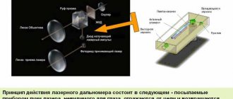
The principle of flaw detection
Diagnostics of welded joints includes various research methods based on the physical properties of metals and structural transformations at the phase transition boundary. The areas under study are exposed to radio waves, ultrasound, magnetic electrostatic field, and dyes. Heterogeneous structures perceive impact differently. The principles for detecting defects are matched to the metal. For example, non-magnetic alloy steels and non-ferrous metals cannot be tested in a magnetic field. Echolocation is ineffective for coarse-grained structures.
Flaw detection of welded joints is a set of quality control methods visually or using special equipment to identify a defect. The principle of flaw detectors and diagnostic methods are approved by standards. Based on the results of flaw detection, the strength (operational reliability) of welds is determined after completion of the work.
Important!
Each welder is responsible for compliance with the technology.
Types of tests performed
Ultrasonic flaw detectors can be used in a variety of applications where non-destructive testing and analysis is required. The type of testing performed varies depending on the application. There are two main methods of control - using direct transducers or inclined ones.
Control using direct converters (P111, P112)
Direct beam testing is typically used to detect cracks or delaminations parallel to the surface of the item being tested, as well as voids and porosity such as plates, rods, forging parts, castings, etc.
Like all other ultrasonic flaw detection techniques, direct transducer testing uses the basic principle that a wave passing through a medium will continue to propagate until it is scattered or reflected from an interface with another material (or surface), such as air or a gap created by a crack or similar discontinuity.
In this type of flaw detection, the operator ensures that the transducer is in close acoustic contact with the sample and identifies the signal returning from the far wall as well as any fixed reflections originating from geometric structures such as grooves or flanges.
The signal that precedes the bottom signal implies the presence of a crack or void in the test object. Through further analysis, the depth, extent, size and shape of the structure creating the reflection can be determined.
Control using inclined transducers (P121, P122)
Although direct beam methods can be very effective in finding defects, they are often not effective when testing welds where discontinuities are not typically oriented parallel to the surface of the part. The combination of weld geometry, defect orientation, and weld presence require inspection from the weld side using an inclined transducer.
These tests are by far the most commonly used ultrasonic flaw detection method. Inclined ultrasonic probes (P121-5-70) consist of a prism and a piezoelectric element, which are built into one housing. They use the principle of refraction and transformation of sound waves at an interface to produce refracted shear or longitudinal waves in the sample.
Defects that are accurately recorded by an ultrasonic flaw detector
One of the most common methods for identifying defects is ultrasonic testing, in which sound waves propagated through a material are used to identify such defects. Ultrasound behaves predictably when interacting with surfaces and internal defects.
The most common discontinuities that an ultrasonic flaw detector can detect are:
- Cracks;
- Voids and shells;
- Chips;
- Porosity in metals, ceramics and plastics;
- Bundles;
- Poor quality welds;
- Corrosion;
- Metal wear
- Inconsistency of metal thickness with the requirements of those conditions.
Main manufacturers and popular models of flaw detectors
There is a large selection of ultrasonic testing devices on the Russian market, which differ in parameters, functionality and price. The table shows the characteristics of some popular models of ultrasonic flaw detectors.
| Model | Maximum length of controlled material (steel) | Gain adjustment range | Speed range | Operating temperature range | Display size and resolution | Scan | Memory | Battery life | Weight |
| Ultrasonic flaw detector USD-60 | up to 3000 mm (echo mode), 6000 mm (shadow mode) | 100 dB | 1000 – 10,000 m/s | from -30ºC to +55°C | Color, TFT 640 x 480 dots (135 x 100 mm). | min: 0 - 11.9 mm max: 0 - 5950 mm (steel) | 200 settings with A-signal 1000 control protocols | 6-8 hours from batteries | 1.4 kg with batteries |
| USD-60FR (phased array) | 2900 mm (steel 5950 m/s) | 80 dB | 2300 - 10,000 m/s | from -30ºC to +55°C | Color high contrast, TFT 640 x 480 pixels, (130 x 100 mm). | min: 0 - 5 mm max: 0 - 600 mm in increments of 0.1, 1, 5, 10 mm | 200 settings with A-signal 1000 control protocols | at least 10 hours from the built-in battery | 1.4 kg with batteries |
| USD-50 IPS | up to 4500 mm (echo mode), 9000 mm (shadow mode) | 100 dB | 1000 - 10,000 m/s | from -30ºC to +55°C | Color high contrast, TFT 640 x 480 pixels, (130 x 100 mm). | min: 0 - 2 µs max: 0 - 1530 µs in steps of 0.01, 0.1, 1, 10 and 100 µs | 200 settings with A-signal 1000 control protocols (signal, envelope, measurement result, device operating parameters, date, time and protocol name) | 10 hours of operation from the built-in battery | 1.4 kg with batteries |
| A1214 EXPERT | 3500 mm | 100 dB | 1000÷15000 m/s | from -30º to +55 ºC | color TFT | 8 hours | 1.9 kg |
Advantages and disadvantages
Advantages:
- low labor intensity of research, connections are controlled by one person within a few minutes;
- safety of monitoring, only radiation diagnostics assumes the influence of harmful factors;
- a variety of monitoring devices; mobile flaw detectors are produced for basic flaw detection methods;
- variety of controlled objects: flat, three-dimensional parts, pipes are checked;
- control of seams produced by any type of welding machine.
Flaws:
- each method has certain limitations on its use due to the identified shortcomings;
- the need to use special reagents and consumables;
- it is necessary to specially prepare the surfaces being examined;
- After diagnostics, controlled fragments must be additionally treated with anti-corrosion agents; when removing scale and oxide film, the protective properties of the metal deteriorate.
Basic flaw detection methods
There are two types of connection defects:
- visible ones are detected during visualization;
- hidden (internal) are determined by flaw detection of welds.
There are destructive testing methods; they are necessary when developing welded joint technology. The phase transition zone is dissected and the metal structure is examined under a microscope.
Non-destructive flaw detection of welds was created to determine the quality of welding. The metal is checked for permeability and homogeneity using modern methods and instruments.
Visual inspection
Welds are checked on site. This is the most commonly used control method. Analyzing the condition of the seam bead, defectoscopy reveals lack of penetration. They are manifested by unevenness of the surfacing layer, cracks, and porosity. To ensure the accuracy of the result, before inspection, remove scale from the seam and wipe the surface of the roller with a solvent (technical methanol). Then the metal is etched with 10% nitric acid, which dissolves the oxide film. Residues of acid are removed with alcohol.
Physical foundations and methods of ultrasonic flaw detection.
Ultrasonic testing (UT) refers to an acoustic type of non-destructive testing, based on the analysis of the results of the interaction of sound waves with the test object (OK) => UT refers to active testing methods (implies an impact on the OC and subsequent analysis of changes in the primary effect to characterize defects).
The whole variety of acoustic methods of non-destructive testing is based on the interaction of elastic media (liquid, solid and gaseous) with acoustic vibrations and waves. They differ in the methods of excitation of vibrations and their registration.
Among the acoustic methods, the most commonly used are ultrasonic flaw detection (USD), ultrasonic thickness gauging (UT) and acoustic emission non-destructive testing. In world practice, ultrasonic testing currently accounts for 60% of the total volume of non-destructive testing.
Acoustic vibrations and waves
Acoustic vibrations are mechanical vibrations of particles of an elastic medium. The processes of propagation of these vibrations in a medium are called acoustic waves. The line indicating the direction of wave propagation is called a ray, and the boundary between oscillating particles and non-oscillating particles is called the wave front.
Acoustic vibrations are characterized by frequency, intensity and type. The types of vibrations are mainly determined by the properties of the elastic medium and the method of their creation. In liquids and gases that have volume elasticity, acoustic vibrations propagate at the same speed in all directions. In solids, which, in addition to volume elasticity, are also characterized by elasticity of shape (shear elasticity) and uneven tension-compression strains in different directions (for anisotropic bodies), the patterns of propagation of acoustic waves are much more complex.
Oscillations with a frequency of up to 16…20 Hz are called infrasonic. Oscillations with a frequency from 16...20 to (15...20)103 Hz constitute the audibility range perceived by the human ear. When the vibration frequency of sound increases above 20 kHz, it turns into ultrasound; At the same time, its ability to spread changes: in air the ability to spread decreases, in solid and liquid media it increases. For non-destructive testing of metal materials, ultrasonic frequencies of 0.5...25 MHz (500...25000 kHz) are used.
The propagation of an acoustic ultrasonic wave in a material occurs at a certain constant speed C, determined by the properties of the medium. Wave propagation is accompanied by the formation of zones in the material in which the particles are in the same vibrational state (phase). The minimum distance between such zones is called wavelength. The quantity is related to the propagation speed C and the oscillation frequency f by the expression
.
The ultrasonic wavelength in a particular material can only be changed by changing the frequency f of the excited vibrations.
The direction of particle oscillations in solids can be different with respect to the direction of wave propagation. Depending on the nature of particle displacement and the propagation of vibrations, waves come in several types.
The nature of the deformation of solid bodies during the propagation of elastic waves of certain types in them (the magnitude of the deformation of the body is very small and is measured in fractions of a percent of the wavelength):
a - longitudinal (tension-compression);
b - transverse (shear).
Waves are called longitudinal when particles of an elastic medium oscillate in the direction of propagation of the wave, while being alternately subjected to tensile-compressive deformations.
The longitudinal wave speed is determined by the formula
, where E is the elastic modulus; - Poisson's ratio; — density of the medium.
If the particles of the medium oscillate perpendicular to the direction of propagation, experiencing shear deformations, such waves are called transverse or shear waves. Transverse waves can only arise in solid media that have shear elasticity. Shear wave speed
.
| Distribution environment | Wave type (name) | Wave characteristic | Spread speed |
| Liquid or gas | Longitudinal (tension-compression) | Periodic expansion and contraction of the medium | WITH |
| Boundless Solid (Steel) | Longitudinal (expansion-compression, irrotational) | Particles oscillate in the direction of wave propagation | |
| Transverse (shear, equivoluminal) | Particles oscillate in a plane perpendicular to the direction of wave propagation |
When carrying out ultrasonic testing and ultrasonic testing of metal and welded joints, transverse and longitudinal waves are mainly used.
Ultrasound attenuation
The propagation of an ultrasonic wave caused by the oscillatory movements of excited particles due to elastic forces between them is accompanied by energy transfer. The amount of energy transferred by a wave in 1 s through 1 cm2 of area perpendicular to the direction of propagation is called ultrasound intensity. The intensity of ultrasonic vibrations of particles is usually low (the wave energy is no more than 100 W/cm2 and does not go beyond the limits of elastic deformations, where stress and deformation are related linearly.
The intensity of ultrasound decreases as it passes through the medium due to its wave impedance z. The value of this resistance, often called characteristic impedance, depends on the density of the medium, the speed of propagation of waves C and is determined by the expression
.
Ultrasound intensity J is proportional to the square of the elastic displacement amplitude and the square of the oscillation frequency
,
where A is the amplitude of elastic displacement of particles of the medium; f is the oscillation frequency.
From the last expression it follows that the greater the acoustic resistance of a medium, the greater the energy required to excite waves of a given frequency and amplitude in it. As the wave passes from the radiation source, the amplitude of the elastic displacement of particles decreases and the intensity of the ultrasound decreases. Intensity decay occurs for two main reasons: absorption and scattering. The attenuation coefficient accordingly consists of two terms
,
where is the absorption coefficient, determined by the viscosity of the medium and the oscillation frequency; — scattering coefficient, depending on the structure, orderliness of arrangement and size of crystal grains.
Absorption is the process of converting vibration energy into heat, caused by friction of vibrating particles. The higher the oscillation frequency, the greater the absorption.
During scattering, refraction and transformation of ultrasonic waves occur. Scattering is due to the crystal structure of metals and alloys. When an ultrasonic wave passes through the boundaries of crystals, the wave is partially reflected, refracted and transformed. Dispersion for these reasons can be significant. Maximum scattering occurs at , where is the average grain size.
The decrease in ultrasound intensity due to its attenuation, depending on the distance traveled in the material, occurs according to an exponential law
,
where is the intensity of ultrasound at a distance x from the radiation source, the radiation intensity of which ; — attenuation coefficient.
The greater the attenuation coefficient, the greater the attenuation of ultrasound, and therefore, the less depth of its penetration. Since the wave amplitude is proportional to the square root of the ultrasound intensity (), the effect of attenuation on the amplitude is described by the formula
.
To estimate attenuation, in most cases it is not necessary to determine the intensity J or amplitude A in absolute units. More often it is enough to determine their value relative to some constant (reference) level. In this case, to express the relative value, special units are used - decibels. The number of decibels dB is determined by the formulas
.
In ultrasound practice, when the ratio of oscillation amplitudes is controlled, the second formula is usually used to determine dB.
Various methods of ultrasonic testing differ in the installation schemes of the emitter and receiver of ultrasonic vibrations, and their position relative to the test object. Apply:
The most widely used pulse echo method is based on the reflection of ultrasonic vibrations from a discontinuity and the reception of reflected echo signals. The amplitude of the echo signal on the flaw detector screen will be proportional to the size of the defect.
Selecting a method
The main parameters of the seams under study are taken into account:
- physical characteristics;
- thickness and dimensions of workpieces;
- surface condition: for ultrasound, cleaning with contact lubricant is required, for the magnetic resonance method, the seam is upset (surface stress is removed), for capillary examination, a perfectly flat and cleaned surface is required.
When choosing a flaw detection method, you must consider:
- the sizes of permissible defects, the sensitivity of the devices is selected according to the technical conditions;
- research conditions.
If it is important to identify volumetric defects and voids, it is more reliable to carry out radiation monitoring. Cracks and lack of penetration are determined by ultrasound and a magnetic field. Defects that appear on the surface are detected using the capillary method.
Capillary flaw detectors
A capillary flaw detector is a set of capillary non-destructive testing devices. Penetrant flaw detection methods make it possible to detect with the naked eye thin surface cracks and other discontinuities in the material that form during the manufacture and operation of machine parts. The cavities of surface cracks are filled with special indicator substances (penetrants), which penetrate into them under the action of capillarity forces. For the so-called luminescent method, penetrants are based on phosphors (kerosene, noriol, etc.).
Story
The first flaw detectors operating on continuous sound were created in 1928 by S. Ya. Sokolov and in 1931 by Mühlhäuser. 1937-1938 - the world's first flaw detector using alternating current to control railway structures and wheel sets (MAGNAFLUX company, USA). Echo-pulse flaw detectors (principle of operation and device) were created for the first time in 1939-1942 by Firestone in the USA, Sprules in the UK and Kruse in Germany. The first echo-pulse flaw detectors were released in 1943 almost simultaneously (Danbury, USA) and Kelvin and Hughes Ltd. (London) source: ru.wikipedia.org