For operational visual inspection of welding joints, a special meter with several graduated scales has been developed. A welder's template is necessary for independently checking important parameters that affect the strength of seams: bevel angle of edges, gap of joints between workpieces, parameters of the seam bead. This is the simplest instrument for non-destructive testing, made of stainless metal, the marks are applied with wear-resistant paint.
Universal welder template USHS-3
Description
The operating principle of templates is mechanical.
The template consists of a base on which a slider with a pointer fixedly mounted on it is mounted using an axis. The engine can rotate relative to the base on the axis. The engine is made in the form of a plate, one end of which is made in the form of a wedge. A scale is applied to the front surface of the wedge part of the engine to control the gap between the parts being welded. At the wedge end of the slider there is a mark, which is an index for measuring the depth of cutting to the root layer, the excess of the edges, and the height of the seam reinforcement. There are also grooves on the base that allow you to control the diameters of the electrodes used. Measurements of the height of the blunting and the width of the seam are made using a scale marked on the base of the template. On the base of the template there is also a scale for measuring the bevel angle of the edges.
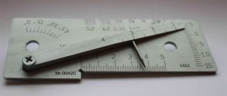
The general view of the template is shown in Figure 1.
Figure 1 - General view of the UShS-3 universal welder template. Sealing of the UShS-3 universal welder templates is not provided.
Template UShS-3
The universal welder template UShS-3 is designed to control weld preparation elements, electrodes and welded joint elements. The UShS-3 template allows you to control the depth of cavities, nicks, excess of edges, the depth of the joint to the root layer, the height of the reinforcement of the seam, control of the gap, the bluntness of the seam, the width of the weld, the bevel angles of the edges, as well as the diameters of the electrodes. The template UShS-3 is produced in accordance with the technical requirements of GOST 15150, in accordance with TU 26.51.33-001-01-2017 “Universal welder template UShS-3. Technical conditions". High-quality tool steel is used for its manufacture, and all parts have a wear-resistant anti-corrosion coating. As a result, the instrument is guaranteed to function and be accurate even after 10,000 measuring cycles. The welder's template UShS-3 is included in most VIC kits. It is possible to supply the UShS-3 template with a certificate of verification of the CSM or a certificate of calibration from the metrological service, or without metrological certification.
Welder template UShS-3. Device:
The template consists (see figure) of a base 1, on which, using an axis 4, a slider 2 is mounted with a pointer 3 fixedly fixed on it. On the front surface of the base 1 there are scales that allow you to measure the following elements of the weld: (D) depth of defects, depth cutting to the root layer, excess of edges, height of seam reinforcement, (D) bevel angle of edges, (E) amount of seam blunting. The engine 2 is made in the form of a plate, one end of which is made in the form of a wedge. On the front surface of the wedge part of the engine there is a scale I, and the scale numbers correspond to the thickness of the engine in a given section (thickness varies from 0.5-4 mm). This profile of the engine allows you to measure the gap between the parts being welded using a scale (I). At the wedge end of the slider there is a mark (K), which is an index for the scale (G). The grooves allow you to control the diameter of the electrodes and wire used.
Welder template UShS-3. Specifications:
| Name of measurements | Measuring range | Value of division | Error limit |
| Seam depth, mm | 0-15 | 1,0 | ±0,5 |
| Reinforcement height, mm | 0-5 | 1,0 | ±0,5 |
| The size of the blunting and width of the seam, mm | 0-50 | 1,0 | ±0,15 |
| Gap size, mm | 0,5-4 | 0,5 | ±0,25 |
| Bevel angles of edges, degrees | 0-45° | 5,0 | ±2,5 |
| Diameter of electrodes, mm | 1; 1,2; 2; 2,5; 3; 3,25; | ±0,1 | |
| 4; 5; | ±0,3 | ||
| Template dimensions | 127x45x9 mm | ||
| Material | stainless steel | ||
| Weight | 160 g | ||
Welder template UShS-3. Taking measurements:
- Measuring the depth of the cavities, the depth of the nicks, the excess of the edges, the depth of the joint to the root layer and the height of the seam reinforcement is carried out when installing the template with surface A on the product. Then, by turning the slider 2 around axis 4, it is necessary to bring pointer 3 into contact with the surface being measured. The result is read against the K risk on the G scale.
- The gap is measured by inserting slider 2, its wedge-shaped part, into the gap being measured. The result is read on the I scale.
- Measuring the bluntness and width of the seam is done using the E scale as a measuring ruler.
- The bevel angles of the edges are measured when the template with surface B is installed on the product generatrix. Then, by turning the slider, surface B moves with the surface being measured. The result is read on a scale D against the surface of the slider B.
- Determination of wire diameters is carried out using grooves G.
Contents of delivery:
- Universal welder template USHS-3;
- Passport;
- Case;
- Certificate of calibration (on request);
- Certificate of verification (upon application).
Related products:
- VIC kits (Expert, Attorney, Transneft, Basic, VIC-1, etc.);
- Roughness meters (TIME, PCE, Elcometer, roughness samples and kits, etc.);
- Luxmeters and radiometers (TKA, Testo, CEM, PCE, etc.).
Specifications
Table 1 - Metrological characteristics
| Characteristic name | Meaning |
| Measuring range | |
| — seam defect depth, mm | from 0 to 15 |
| — height of butt weld reinforcement, mm | from 0 to 5 |
| — height of the blunting and width of the seam, mm | from 0 to 50 |
| — gap between parts to be welded, mm | from 1 to 4 |
| — cutting angle (edge bevel), 0 | from 0 to 45 |
| Characteristic name | Meaning |
| Groove width of controlled electrode diameter, mm | 1; 1,2; 2; 2,5; 3; 3,25; 4; 5 |
| Scale division price | |
| — seam defect depth, mm | 1,0 |
| — height of butt weld reinforcement, mm | 1,0 |
| — height of the blunting and width of the seam, mm | 1,0 |
| — gap between parts to be welded, mm | 0,5 |
| — cutting angle (edge bevel), 0 | 5,0 |
| Limits of permissible absolute error | |
| measurements | |
| — seam defect depth, mm | ±0,5 |
| — height of butt weld reinforcement, mm | ±0,5 |
| — height of the blunting and width of the seam, mm | ±0,15 |
| — gap between parts to be welded, mm | ±0,25 |
| — cutting angle (edge bevel),° | ±2,5 |
| Limits of permissible deviation from the nominal | |
| values, mm: | |
| — groove width of controlled diameter | |
| electrodes 1; 1.2; 2; 2.5; 3; 3.25 mm | ±0,1 |
| — groove width of controlled diameter | |
| electrodes 4 and 5 mm | ±0,3 |
Table 2 - Main technical characteristics
| Characteristic name | Meaning |
| Overall dimensions, mm, no more (WxHxD) | 130x45x16 |
| Weight, kg, no more | 0,18 |
| Terms of Use: | |
| — ambient temperature, °C | from +15 to +35 |
| — relative humidity, % | from 45 to 80 |
| — atmospheric pressure, kPa | from 84 to 106.7 |
| Service life, years, not less | 5 |
UShS-3 - universal welder template
The universal welder template UShS-3 is designed to control weld preparation elements, electrodes and welded joint elements. Allows you to control the depth of cavities, nicks, excess of edges, the depth of the joint to the root layer, the height of the weld reinforcement, the control of the gap, the bluntness of the seam, the width of the weld, the bevel angles of the edges, as well as the diameters of the electrodes.
UShS-3 scale parameters:
- material: stainless steel
- scale division price G and E: 1 mm;
- scale division value: 0.5 mm;
- scale division D: 5°;
- permissible deviations in the width of the grooves: up to 3.25 mm - according to H12, over 3.25 mm - according to H14;
- deviation of the position of the jackal strokes G, I: no more than ± 0.5;
- deviation of the position of the scale D from the actual angle value: no more than 2°30′;
- deviation from the nominal value of the distance between any stroke and the beginning of the E scale: no more than ± 0.15;
Operating procedure
Before starting work, rinse the template in gasoline according to GOST 1012-72 and wipe with a clean cloth.
Measurements should be carried out as follows:
- To control the depth of defects (dents, nicks), the excess of edges, the depth of the joint to the root layer and the height of the reinforcement of the seam, place the template on the forming surface of the product with plane A. Rotate the slider 2 around axis 4 until the end of the pointer 3 touches the measured surface (dent surface , seam edges, etc.). Create a report on the G scale using the K mark.
- Check the bluntness and width of the seam using the E scale, using it as a measuring ruler.
- To control the size of the gap between the parts being welded, insert the wedge part of the engine 2 into the controlled gap until it stops. Take a report on the I scale.
- To control the bevel angles of the edges, place the template with plane B on the forming surface of the product. Turn slider 2 until plane B of the slider aligns with the surface being measured. Take a report on the D scale of the base, using plane B of the engine as an index.
- To determine the diameter of the electrodes (electrode wire), it is inserted into the grooves of the template, using the grooves as staple gauges.
Distinctive features
- Control of the depth of seam defects: 0 - 15 mm.
- Seam reinforcement height control: 0 - 5 mm.
- Gap control: 0.5 - 4 mm.
- Control of the amount of blunting and seam width: 0 - 50 mm.
- Control of edge bevel angles: 0 - 45°.
- Control of electrode diameters: 1.0 / 1.2 / 2.0 / 2.5 / 3.0 / 3.25 / 4.0 / 5.0.
UShS-3 with calibration
- universal welder template UShS-3;
- passport;
- case;
- calibration certificate;
- package.
13 €
13 € 11 € from 100 pcs.
DISCOUNT
2
in stock
Buy
UShS-3 without calibration
- universal welder template UShS-3;
- passport;
- case;
- package.
10 €
10 € 9 € from 100 pcs.
DISCOUNT
1
in stock
Buy
Completeness
Table 3 — Completeness of the measuring instrument
| Name | Designation | Quantity |
| Universal welder template | UShS-3 | 1 PC. |
| Passport | — | 1 copy |
| Manual | — | 1 copy |
| Verification method | RT-MP-4939-445-2017 | 1 copy |
Verification
carried out according to the document RT-MP-4939-445-2017 “GSI. Universal welder templates UShS-3. Verification methodology”, approved by the Federal Budgetary Institution “Rostest-Moscow” on December 15, 2021. Main verification tools:
— two-coordinate measuring device DIP-1 (registration number in the Federal Information Fund 7864-80)
— plane-parallel end measures of length 4 categories according to GOST R 8.763-2011
— verification plate 400*400 class 0 according to GOST 10905-86
— caliper ShTs-11-250-0.05 according to GOST 166-89
It is allowed to use similar verification tools that ensure the determination of the metrological characteristics of the verified measuring instruments with the required accuracy.
The verification mark (imprint of the verification mark and/or sticker) is applied to the verification certificate.
Brief instructions
The meter in question is produced in accordance with the technical requirements of GOST 15150. High-quality tool steel is used for its manufacture, and all parts have a wear-resistant anti-corrosion coating. As a result, the instrument is guaranteed to function and be accurate even after 10,000 measuring cycles.
The UShS-3 universal welder template (see Fig. 1) uses the following components:
Fig. 1 – General view of the measuring template
- Main measuring panel.
- Runner with varying thickness.
- Arrow pointer.
- An axis designed to rotate the slider.
- A – installation plane, with which the tool is applied to one of the linear surfaces of the welded part in order to determine the height and width of the seam;
- B – installation plane for measuring the bevel angle of the edge for welding;
- B – movable pointer;
- G – scale for measuring the height dimensions of the seam;
- D – scale for determining the edge bevel angle;
- E – scale for measuring the bluntness and total width of the weld;
- I – scale for determining the gap between the elements being welded;
- G – grooves for measuring metal thickness in the welding zone.
- K – risk index on the slider, which is intended for counting the result on the G scale.
On the main measuring panel of the universal welder template of standard size UShS-3, the following measuring zones and planes are distinguished:
No dents or bends are allowed on the measuring panel. The rotary axis should allow the slider to move smoothly without jamming.
The functionality of the tool is guaranteed within a temperature range of ±45°C. Provided that the template is purchased from a specialized store and periodic accuracy checks are performed, this template ensures measurement accuracy within the following limits and ranges:
A universal welder template of this type can be used when carrying out welding work with electrodes with a diameter of 1...5 mm, while the measurement error ranges from ±0.1 mm (for electrodes whose diameter does not exceed 3 mm) to ±0.12...±0 .3 mm – for electrodes with a diameter of less than 3.25 mm and more than 3.25 mm, respectively.